
Figures & data
Figure 1. (a) Geometry of the two-dimensional computational model built (not to scale). Dimensions of cardiac tissue and blood (X = Y = 40 mm) were obtained from a convergence test. Cardiac tissue thickness (T) was 40 mm. RF current flows between an active electrode (7 Fr, 4 mm) and the dispersive electrode (bottom). We considered two active electrode types: non-irrigated and irrigated. The active electrode is assumed to be inserted into cardiac tissue to a depth DE∼0.4 mm. (b) Detail of the mesh used in the model, showing a zoom of the zone with the finest grid size (interface electrode tissue). (c) Electrical and thermal boundary conditions of the model. hE and hT are the thermal convection coefficients at the electrode–blood and the tissue–blood interfaces, respectively. Only in the case of simulating an irrigated electrode, a constant temperature of 45 °C was applied at the electrode tip but not in the part inserted in the tissue.
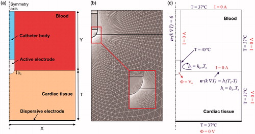
Table 1. Physical characteristics of tissues and materials employed in the computational models (data from [Citation15,Citation16]).
Figure 2. Temperature distributions in the tissue after 30 and 60 s of radiofrequency ablation with (a) a non-irrigated electrode at constant temperature and (b) with an irrigated electrode at constant temperature. Plots correspond to cases in which the blood perfusion term was not included in the bioheat equation. Solid line is the 50 °C isotherm, which can be assumed to be the thermal lesion contour. Dashed line represents the location of this contour when the blood perfusion term is included at a rate of 1719 ml/min/kg (maximum value reported in [Citation17], but very similar to that measured in resting humans (1750 ± 860 ml/min/kg) using perfusion imaging techniques [Citation19]).
![Figure 2. Temperature distributions in the tissue after 30 and 60 s of radiofrequency ablation with (a) a non-irrigated electrode at constant temperature and (b) with an irrigated electrode at constant temperature. Plots correspond to cases in which the blood perfusion term was not included in the bioheat equation. Solid line is the 50 °C isotherm, which can be assumed to be the thermal lesion contour. Dashed line represents the location of this contour when the blood perfusion term is included at a rate of 1719 ml/min/kg (maximum value reported in [Citation17], but very similar to that measured in resting humans (1750 ± 860 ml/min/kg) using perfusion imaging techniques [Citation19]).](/cms/asset/f594b63d-3a3a-4f6b-bc17-197689616f1a/ihyt_a_1336258_f0002_c.jpg)
Figure 3. Progress of applied power (between 6 and 7 W) in the case of constant power ablation and electrode temperature (50 °C target) in the case of constant temperature ablation.
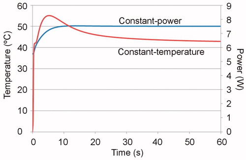
Table 2. Thermal lesion depths (in mm) computed for the cases with and without blood perfusion term at 30 and 60 s. The applied total energy for each case is reported in brackets.