Figures & data
Figure 1. (A) Osteocool RFA system provides three different ablative protocols with standard ablation temperature set at 70 °C; the protocol is automatically selected by the system based on the size of the active tip (7, 10 or 20 mm) of the selected electrode. (B) When two electrodes are activated simultaneously, based on the distance between the two active tips, different sizes and shapes of the ablation area are obtained. The widest ablation area, roughly reproducing the shape of the vertebral body, is obtained when the two tips of the electrodes are spaced away 8–10 mm.
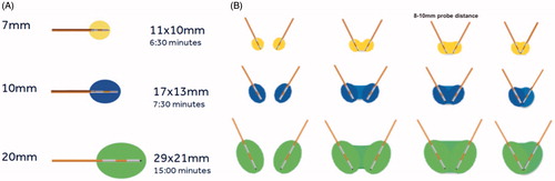
Figure 2. Bilateral double-probe approach performed with the “drill-kissing” technique. (A, B) The vertebral body is bilaterally accessed with 10–13 G bone trocars; the distal tips of the trocars are deployed just behind the posterior margin of the tumour; and the line connecting the tips of both trocars corresponds to the posterior margin of the ablation area. (C, D) Bone drilling is thereafter performed coaxially to create a channel to allocate the electrodes; the distal tip of the drills is advanced just anteriorly to the anterior margin of the tumour with a “drill-kissing” configuration; the line passing through the distal tips of the drills corresponds to the anterior border of the ablation area. (E) Final configuration of electrodes deployment with their distal tips spaced away 8–10 mm. (F) Axial T1-weighted CE-MRI sequence showing the size of the ablation area (*) roughly reproducing the shape of the vertebral body. (G) Reconstructed image showing the expected ablation area based on the configuration of electrodes deployment. (H) Reconstructed image showing the ablation area obtained at 24-h CE-MRI based on the configuration of electrodes deployment.
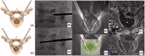
Figure 3. (A) Painful metastatic involvement of L2 (*) in a 77 years old female patient affected by bladder cancer. (B) Two 20 mm active tip RFA electrodes were deployed through a trans-pedicular approach and several different impacts were performed. (B, C) A thermocouple was deployed through a descending trans-foraminal approach (white arrow); epidural hydro-dissection was performed through the same approach (black arrow). (D) Vertebral augmentation was subsequently performed. (E, F) Contrast enhanced T1-weighted sequence obtained 24 h after RFA shows the extension of the necrotic area (*).
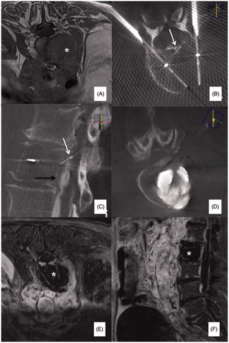
Figure 4. (A, B) Primary painful L3 chondrosarcoma (*) severely compressing the dural sac in a 61 years old female patient confined to a wheelchair; a bi-pedicular involvement is also present (white arrows) thus, making the lumbar spine instable. (C) Two 20 mm active tip RFA electrodes were deployed through a trans-pedicular approach and several different impacts were performed. A thermocouple was also deployed through a posterior inter-laminar approach (black arrow) to monitor the temperature rise at the level of the posterior wall; during ablation some gas bubbles increasing the impedance and thus limiting RFA energy delivery were noted (white arrows); accordingly, some drops of saline were injected to boost RFA, which was then conducted uneventfully. (D) Vertebral augmentation was subsequently performed, followed by (E) surgical laminectomy and stabilisation. The patient was pain free and able to walk again for 5 months until new local tumour progression occurred.
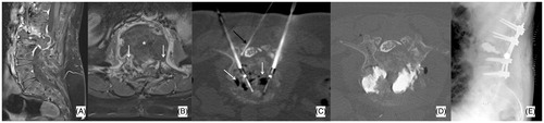
Table 1. Study population.
Table 2. RFA data.
Figure 5. (A) Slow-evolving S1 lytic metastasis (*) in a 58 years old male patient affected by a neuroendocrine cancer of the lung; the patient presented with low back pain and bilateral sciatica due to bilateral involvement of S1 neuroforamina (white arrows); a vertical pathologic fracture was also noted (black arrow). (B) Two 20 mm active tip RFA electrodes were deployed (black arrows) and several different impacts were performed. Furthermore, four thermocouples were deployed (white arrows): one in each neuroforamen and one behind each electrode to monitor the temperature rise in both neuroforamina and at the level of the posterior wall. (C, D) Following RFA, two cannulated screws were deployed to fix the fracture; moreover, PMMA was also injected to fill the lytic cavity and to anchor the tip of the screws in distal healthy bone (white arrows).
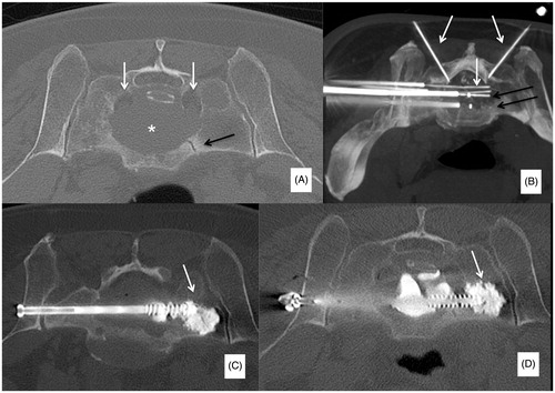
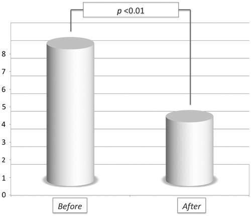
Figure 6. Pain drop following RFA and vertebral augmentation.