
Figures & data
Figure 1. Experimental setup to produce lesions in ex vivo tissues on a clinical MR-HIFU system. The setup consisted of a water bath, filled with degassed water and a closed-loop heating coil that circulated heated water to maintain the water bath temperature at 37.5 °C. A custom-designed tissue holder was positioned at a fixed distance from the transducer. The water bath was placed on the patient tabletop’s acoustic window. Each tissue sample (45 mm in thickness) was sonicated using a 3 × 3 grid pattern with 1 mm spacing between foci in either direction.
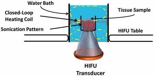
Table 1. List of MRI pulse sequences and their respective parameters applied during histotripsy experiments.
Table 2. Sonication parameters used in the experiments for all tissue types.
Figure 2. Lesions produced in ex vivo porcine liver tissue using sonication parameter sets F, A and D with their corresponding H&E stains are illustrated in a, b & c panels, respectively. These lesions display significantly different morphologies. a1. Thermal map showing temperatures greater than 60 °C in the focal region. a2. Shows a solid thermal lesion (green dotted circle) with mechanical disruption of tissue at the centre of the focal region, surrounded by whitening of tissue. a3. Shows H&E stain with green arrow pointing to the necrosed region of liver. a5. Arrowhead pointing to individual injured cells at the edge of the treatment region. b1. Thermal map displaying temperatures no greater than 50 °C at the focal region, with minimal or no temperature change surrounding this region. b2. Lesion consists of a paste-like tissue in the focal region (yellow dotted lesion) surrounded by a sharp boundary of intact tissue. b3. Shows area of missing tissue in the H&E stain due to loss of the paste during stain process. b4. Region of both intact and necroses tissue. b5. Yellow arrowhead points to hepatic cells partially or completely ruptured. c1. This lesion consisted of the greatest area of temperature, but did not have temperatures increase greater than 55 °C. c2. Displays a vacuolated lesion at the focal region (red dotted circle) with intact tissue around the lesion. c3. Red arrow shows region of vacuolated tissue with intact surrounding tissue. c4&5. Region of intact tissue and vacuolated tissue with red arrowhead pointing to the edge of the lesion that is intact post sonication.
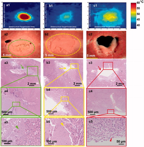
Figure 3. Gross pathology along with H&E and vimentin stains created using sonication parameter sets F (panels a & b) and C (panels c & d). Vimentin stains for mesenchymal cells and is a surrogate for tissue viability. Panel b shows substantial damage of tissue beyond the focal region (panel b2, yellow arrowhead) even though H&E indicates intact tissue (panel a3 green arrowhead). In contrast, panel c shows structurally intact tissue around the focal region and panel d depicts viable tissue in this intact region (green and yellow arrowheads in panels c3 & d2 respectively).
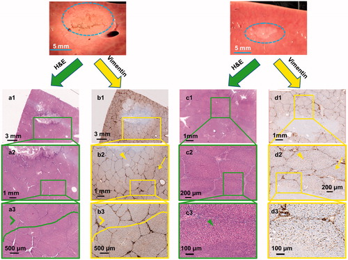
Figure 4. Gross pathology along with H&E stains of lesions produced using sonication parameter set F in porcine liver, kidney, and heart tissues in panels a, b and c, respectively. While the liver tissue expressed solid thermal damage, the kidney presented a paste-like lesion at the focal region. The cardiac muscle showed substantial mechanical fractionation, with some thermal effects along the lesion border.
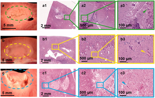
Figure 5. Column chart showing area of temperature greater than 45 °C along the coronal (panel i) and sagittal (panel ii) planes. Statistically different area of temperature was found between D and all other parameter sets, consistent with measurements made along the sagittal plane. Area of temperature was higher along the sagittal plane compared to the coronal plane since the focus region is longer along the sagittal plane than in the coronal plane.
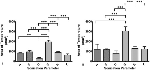
Table 3. Descriptions of sonication parameter-dependent lesions in ex vivo porcine liver, kidney and cardiac muscle tissues.
Figure 6. Summary of the varied sonication parameters along with area of lethal thermal dose and corresponding gross pathology images of liver tissue. Area of thermal dose is quantified along the coronal plane and displayed in bar-graph format. Parameter set D was significantly different compared to all other parameter sets. There were additional differences between other sonication parameter sets. Although the area of lethal thermal dose was similar between parameter sets A, B, E and F, the lesions produced were different in structure, as seen in the gross pathology images.
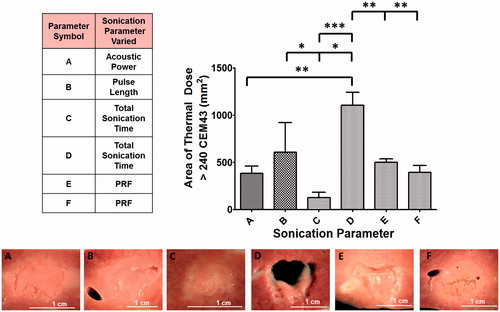
Figure 7. Examples of T2-weighted MR images of ex vivo porcine heart and liver obtained post-sonication using parameter sets A (panel A) and D (panel B). The images reveal a square-shaped hyperintense region (yellow circle) consistent with the square sonication grid pattern and with the square fractionated and partially liquefied lesion. Image in panel B also reveals nine spatially distinct points consistent with the sonication grid. (Colored version is available on the journal’s webpage).
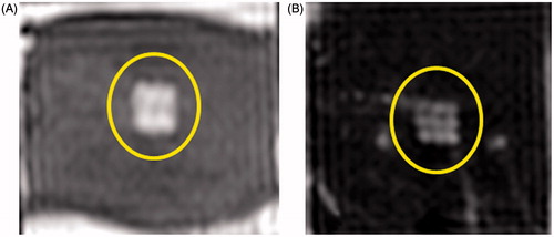
Table 4. T2 relaxation times inside and outside the sonication region in liver tissue for all sonication parameter sets.