Figures & data
Figure 1. Schematic representation of the capacitive and radiative heating systems and the phantoms used in the simulations. The AMC-4 system consists of four rectangular waveguides, which were positioned around the phantom. Capacitive electrodes were positioned at the top and bottom of the phantom, at the sides, or alternatingly at the top and bottom and at the sides.
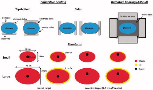
Figure 2. Transversal cross-sections of the CT scans for small (i.e. slender) and large (i.e. overweight/obese) cervix, prostate, bladder and rectum cancer patients. The scans of the cervix and bladder cancer patients were standard hyperthermia treatment planning scans for heating with the AMC-4 system, scanned in treatment position, i.e. on a water bolus and mattressess. The prostate and rectum cancer patients were not treated with the AMC-4 system and standard radiotherapy scans were used, recorded on the table of the linear accelerator. Measured fat layer thicknesess are indicated and the red contour represents the target region. Cross-sections are at the centre of the target region in axial direction.
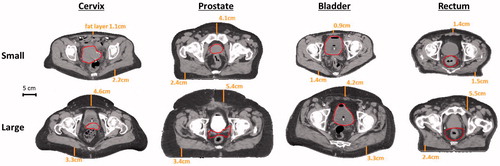
Table 1. Values of the dielectric properties at 13.56 MHz and 70 MHz used in the simulations [Citation46]; conductivity (σ [S m−1] and relative permittivity (εr [−]).
Table 2. Values of the density and thermal properties used in the simulations [Citation47]; density (ρ [kg m−3]), specific heat capacity (c [J kg−1 °C−1]), thermal conductivity (k [W m−1 °C−1]) and perfusion (Wb [kg m−3 s−1]).
Figure 3. Simulated T90 target temperatures for small (A + B) and large (C + D) homogeneous phantoms, with a central or eccentric target volume, heated by two 25 cm diameter capacitive electrodes with different boluses (saline, distilled water, saline + overlay bolus) or the radiative AMC-4 system. Capacitive electrodes were positioned at the top and bottom of the phantom, at the sides or alternatingly.
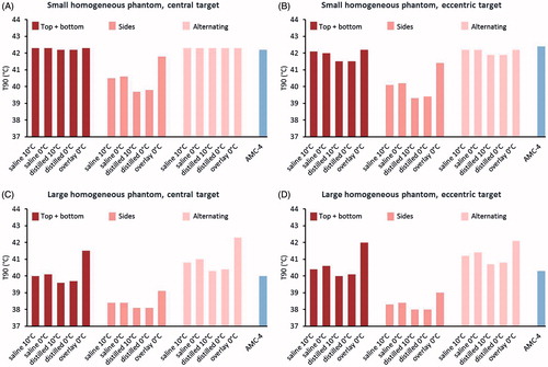
Table 3. Power contribution and phase settings for the antennas of the AMC-4 system, as numerically optimised to simulate target heating with the highest T90, with constraints of 44 °C to all tissues.
Figure 4. Simulated T90 target temperatures for small (A + B) and large (C + D) homogeneous phantoms, with a central or eccentric target volume, heated by different combinations of capacitive electrodes (diameters 25 + 25 cm, 20 + 25 cm or 15 + 25 cm) with different boluses (saline, distilled water, saline + overlay bolus) or the radiative AMC-4 system. Capacitive electrodes were positioned at the top and bottom of the phantom.
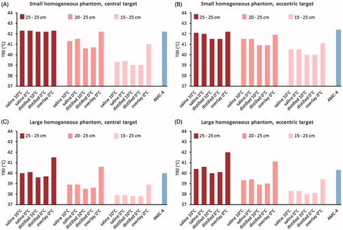
Figure 5. Simulated temperature distributions for heating of the homogeneous phantoms with capacitive electrodes (25 + 25 cm) using overlay boluses and the radiative AMC-4 system. The maximum temperature in all distributions is 44 °C. The total power absorbed in the phantom (Ptot) and in the target region (Ptarget) is indicated for each distribution.
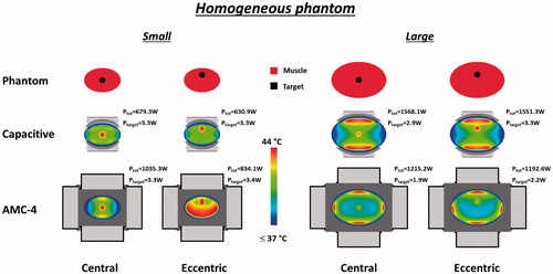
Figure 6. Simulated T90 target temperatures for small (A + B) and large (C + D) inhomogeneous phantoms, with a central or eccentric target volume, heated by two 25 cm diameter capacitive electrodes with different boluses (saline, distilled water, saline + overlay bolus) or the radiative AMC-4 system. Capacitive electrodes were positioned at the top and bottom of the phantom, at the sides, or alternatingly.
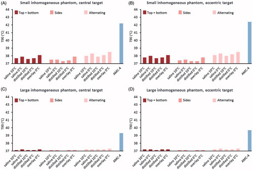
Figure 7. Simulated T90 target temperatures for small (A + B) and large (C + D) inhomogeneous phantoms, with a central or eccentric target volume, heated by different combinations of capacitive electrodes (diameters 25 + 25 cm, 20 + 25 cm or 15 + 25 cm) with different boluses (saline, distilled water, saline + overlay bolus) or the radiative AMC-4 system. Capacitive electrodes were positioned at the top and bottom of the phantom.
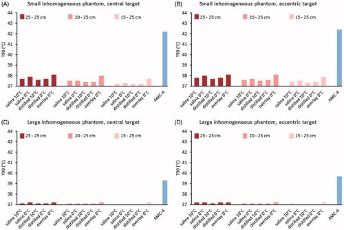
Figure 8. Simulated temperature distributions for heating of the inhomogeneous phantoms with capacitive electrodes (25 + 25 cm) using overlay boluses or the radiative AMC-4 system. The maximum temperature in all distributions is 44 °C. The total power absorbed in the phantom (Ptot) and in the target region (Ptarget) is indicated for each distribution.
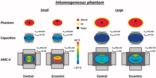
Figure 9. Transient temperature development in the central target region and at a superficial hot spot location at the fat-muscle interface (i.e. at ∼1 cm depth) for capacitive heating of the small inhomogeneous phantom with and without 15 min precooling using a saline bolus at 10 °C.
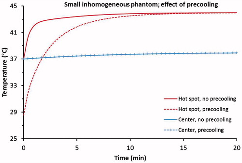
Figure 10. Simulated indexed target temperatures T10, T50 and T90, for small fatless, small and large cervix, prostate, bladder and rectum cancer patients heated with capacitive electrodes using overlay boluses with different combinations of capacitive electrodes (diameters 25 + 25 cm for cervix and prostate and diameters 25 + 25 cm, 20 + 25 cm or 15 + 25 cm for bladder and rectum) or the radiative AMC-4 system.
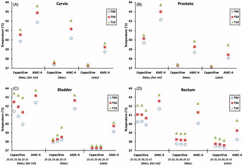
Figure 11. Simulated indexed target temperatures T10, T50 and T90, for small cervix, prostate, bladder and rectum cancer patients with normal electrical conductivity of the target region, or 10% enlarged values of the electrical conductivity. Heating was simulated with capacitive electrodes using overlay boluses with different combinations of capacitive electrodes (diameters 25 + 25 cm for cervix and prostate and diameters 25 + 25 cm, 20 + 25 cm or 15 + 25 cm for bladder and rectum) or the radiative AMC-4 system.
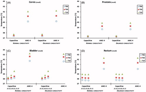
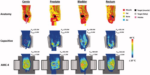
Figure 12. Transversal slices of the simulated temperature distribution for small fatless cervix, prostate, bladder and rectum cancer patients heated with capacitive electrodes (25 + 25 cm) using overlay boluses or the radiative AMC-4 system. The maximum temperature in all distributions is 44 °C. The total power absorbed in the patient (Ptot) and in the target region (Ptarget) is indicated for each distribution. Cross-sections are at the centre of the target region in axial direction. The contour in the temperature distributions indicates the target region.
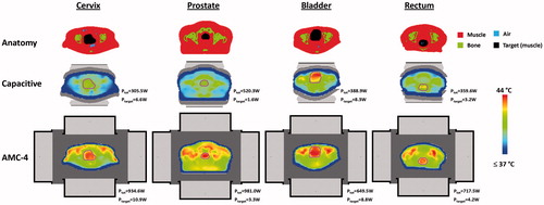
Figure 13. Sagittal slices of the simulated temperature distribution for small fatless cervix, prostate, bladder and rectum cancer patients heated with capacitive electrodes (25 + 25 cm) using overlay boluses or the radiative AMC-4 system. The maximum temperature in all distributions is 44 °C. The total power absorbed in the patient (Ptot) and in the target region (Ptarget) is indicated for each distribution. Slices were taken approximately through the centre of the patient. The contour in the temperature distributions indicates the target region.
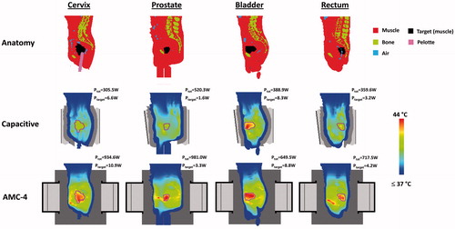
Figure 14. Transversal slices of the simulated temperature distribution for small cervix, prostate, bladder and rectum cancer patients heated with capacitive electrodes using overlay boluses or the radiative AMC-4 system. Electrode sizes top + bottom were 25 + 25 cm (cervix, prostate, rectum) and 15 + 25 cm (bladder). The maximum temperature in all distributions is 44 °C. The total power absorbed in the patient (Ptot) and in the target region (Ptarget) is indicated for each distribution. Cross-sections are at the centre of the target region in axial direction. The contour in the temperature distributions indicates the target region.
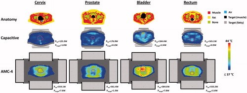
Figure 15. Sagittal slices of the simulated temperature distribution for small cervix, prostate, bladder and rectum cancer patients heated with capacitive electrodes using overlay boluses or the radiative AMC-4 system. Electrode sizes top + bottom were 25 + 25 cm (cervix, prostate, rectum) and 15 + 25 cm (bladder). The maximum temperature in all distributions is 44 °C. The total power absorbed in the patient (Ptot) and in the target region (Ptarget) is indicated for each distribution. Slices were taken approximately through the centre of the patient. The contour in the temperature distributions indicates the target region.