Figures & data
Figure 1. Schematic illustration and photographs of the newly developed hyperthermia device. (A) Schematic illustration of the prototype hyperthermia device used in the pre-clinical animal experiment. The device consists of a (1) water heater and pump, a (2) temperature display monitor, a (3) spherical hyperthermia implant, a (4) temperature sensor line, a (5) water inlet tube, and a (6) water outlet tube. (B) Photograph of the prototype hyperthermia device. Photograph of the (C) anterior (D) lateral and (E) posterior side of the modified hyperthermia device. The (7) temperature display monitor and the (8) control panels were on the anterior side. The (9) water tank was attached on the lateral side. The water would pass through the (10) upper tube from the water tank to the (11) water heater. The heated water would then pass through the lower tube and the (12) water pump. It would ultimately be pumped out through the (13) water outlet tube to heat up the spherical hyperthermia implant. The temperature sensor was connected to the (14) sensor connector. There were (15), (16) fans on the posterior side of the device for cooling.
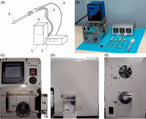
Figure 2. Schematic illustration and photographs of spherical hyperthermia implants and temperature sensor. (A) Schematic illustration of the spherical hyperthermia implant. The implant was heated by circulating heated water into it. The temperature sensor tip extending from the implant had three different channels situated 5 mm apart from one another. (B) Photograph of the hyperthermia implant with temperature sensor. (C) Photograph of hyperthermia implants in different sizes. (D) Photograph of the temperature sensor.
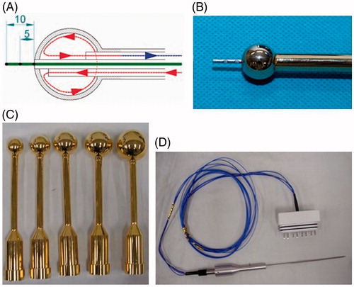
Figure 3. Photographs of the hyperthermia device being applied to a pig in pre-clinical experiment. (A) A total of six pigs were used in the pre-clinical animal experiment. (B) Right frontal craniectomy and partial resection of the frontal lobe were performed on a pig. (C) The hyperthermia device was applied to the surgically made brain cavity. The temperature of the surrounding brain tissues at 5 mm in depth from the cavity margin was elevated to 42.5 °C for a total of 60 min. (D) Photograph illustrating how the hyperthermia device was set up and applied to a pig.
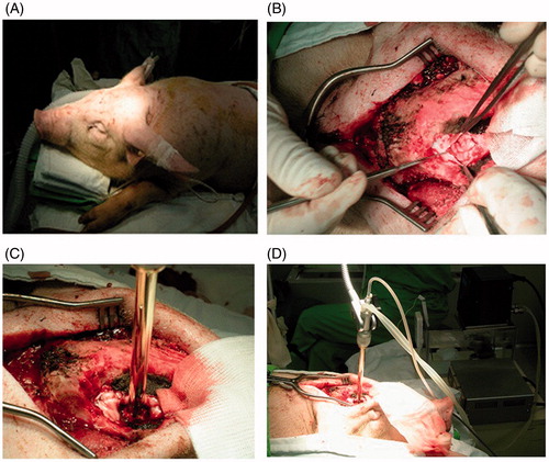
Figure 4. Pathology studies performed on pigs during the pre-clinical animal experiment. (A) Hematoxylin & Eosin (H&E) stain and (B) formalin fixed brain slices of a pig that was terminated immediately after the hyperthermia treatment. Hemorrhage and mild edematous change around the surgical cavity was observed. However, heat-induced degenerative neuronal injury was not observed. (C) H&E stain 40 × (D) H&E stain 100× and (E) formalin fixed brain slices of a pig that was terminated one month after the hyperthermia treatment. Pyknosis and cytoplasmic degeneration surrounded by foam cells and inflammatory cells were observed. Reactive gliosis was observed in the adjacent brain tissues but heat-induced degenerative neuronal injury was not observed.
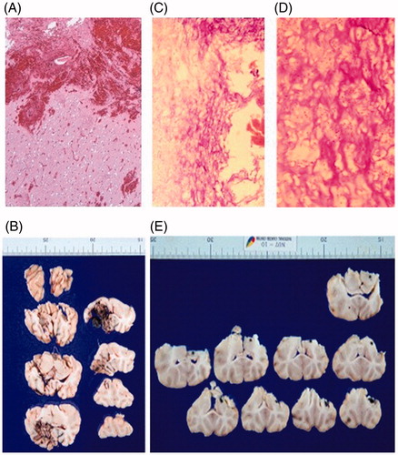
Figure 5. Brain MRI of a pig at one month after the hyperthermia treatment. (A) Axial T2 weighted images (B) Coronal T2 weighted images (C) Coronal T1 weighted images (D) Coronal T1 contrast enhanced images. MRI did not show any significant findings.
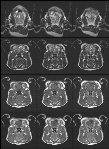
Figure 6. Photographs of the hyperthermia device being applied to a patient during the clinical trial. (A) Photograph illustrating how the modified hyperthermia device was applied to a patient in an operating room setting. (B) The hyperthermia device was applied intra-operatively after total resection of the metastatic brain tumor was performed.
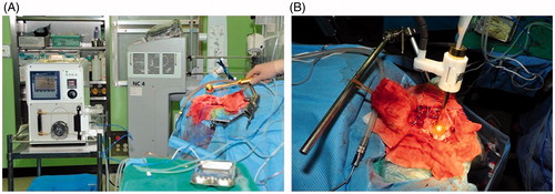
Table 1. Baseline characteristics of the patients by types of treatment.
Table 2. RT regimen and radiation dose by types of treatment.
Table 3. One tailed z-test of local recurrence.
Figure 7. Differences in local tumor recurrence according to types of treatment.
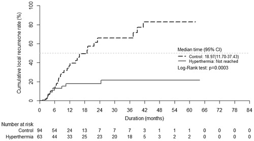
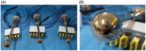
Figure 8. Photographs of modified spherical hyperthermia implants. (A) Photograph of the modified hyperthermia implants in different sizes. (B) The modified implant had five temperature sensors tips extending around the implant to better monitor the temperature of the surrounding brain tissues.