Figures & data
Figure 1. Flowchart summarizes patient inclusion in RFA group.
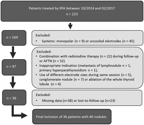
Figure 2. Flowchart summarizes patient inclusion in MWA group.
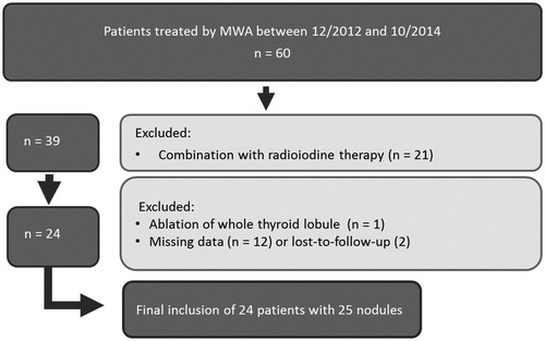
Table 1. Measured data of uncooled MW antennas.
Table 2. Measured data of cooled RF electrodes.
Figure 3. Illustration of different shapes and sizes of thermal ablative zones in thyroid. Left part of the illustration: Cooled RF electrode producing ellipsoid shaped ablation zones. Less heating along the shaft, which results in less damage of passed structures like the skin or M. Sternocleidomastoideus. Heat-sink-effects by large vessels (A and V) protecting contiguous nerve structures such as Vagus nerve (III) or middle cervical sympathetic ganglion (II). Right part of the illustration: uncooled MW antenna inducing ‘tear-drop’ shaped ablation zones as a result of additional heating effects along the shaft. Less heat-sink-effects next to vulnerable structures like middle cervical sympathetic ganglion (II) or Vagus nerve (III) with possible higher risk of unintended harms. I: recurrent laryngeal nerve; II: middle cervical sympathetic ganglion; III: vagus nerve; A: common carotid artery; V: internal jugular vein.
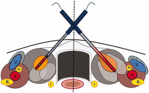
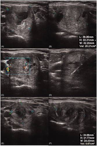
Figure 4. Ultrasound images of a thyroid nodule before bipolar RFA (a and b), during ablation (c and d) and three months after ablation (e and f).
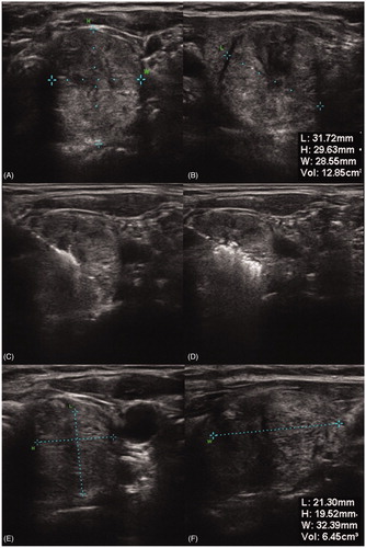
Figure 5. Ultrasound images of a thyroid nodule with central blood perfusion and surrounding cervical vessels (c), before MWA (a and b), during ablation (d) and three months after ablation (e + f).