Figures & data
Figure 1. Concept diagram of proposed treatment strategy for ablation of lung tumors adjacent to major and sub-segmental tertiary bronchi using endobronchial ultrasound applicators: larger diameter applicator configurations composed of planar or sectored tubular transducer segments for treatment of tumors at large airways, and smaller diameter applicators with tubular sources for targeting tumors adjacent to deep lung sites.
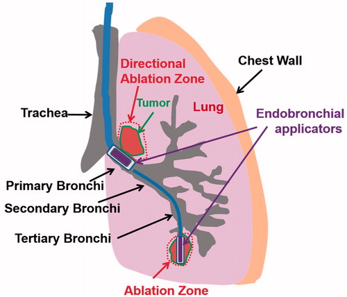
Figure 2. Design schema of endobronchial ultrasound applicators for thermal treatment of lung tumors adjacent to major bronchi and deep lung. Ultrasound transducer applicator configurations include (1) planar transducer, (2) fully active (360°) tubular transducer, and (3) angular sectored (120° or 150° active sector) tubular transducer, each integrated within an expandable balloon for coupling and water cooling.
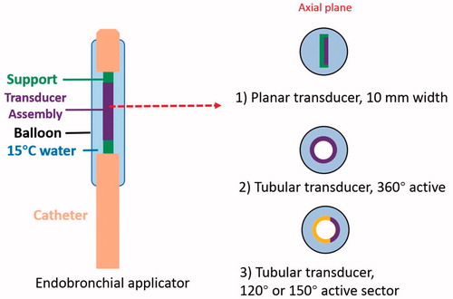
Table 1. Thermal and acoustic properties of tissues used in the parametric study and patient specific simulations.
Figure 3. 2D parametric simulation models with attaching (Model A) and adjacent but not attaching tumors (Model B) to the bronchial wall: transducer types (planar, 360° active tubular applicators), tumor sizes (0.5–3 cm, as denoted by yellow arrowed bar) and lung environments (lower and higher inflated lung, flooded lung) were varied to represent different treatment sites and conditions, as listed in .
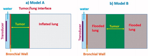
Table 2. Endobronchial ultrasound applicator configurations and tumor location with dimensions investigated within parametric studies, for tumors attached and unattached to the bronchial wall, and with and without lung flooding.
Figure 4. Overview of 3D patient-specific lung bronchi/airway anatomy generated for Models 1–5, each incorporating a distinct tumor geometry/position and lung environment (higher inflated, lower inflated, and flooded lung).
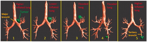
Table 3. Details of anatomical lung and tumor models and applicator configurations for patient-specific simulation studies.
Figure 5. Parametric study: comparison of penetration depths (52 °C margin) of endobronchial ultrasound applicators in planar (10 mm width ×20 mm length transducer, 10 mm balloon OD, top row) or tubular configurations (10 mm balloon OD, bottom row) at 3–9 MHz for treatment of lung tumors varying from 10 mm (left) to 30 mm (right) depth attached to major airways. Two lung conditions (higher and lower inflated lung, represented in red and blue, respectively) were considered. The effective ablated zone extends between min-depth and max-depth, as depicted. BW: bronchial wall.
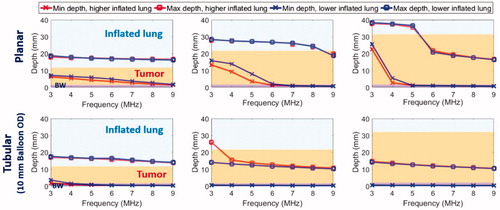
Figure 6. Parametric study: comparison of penetration depths (52 °C margin) of two sizes of endobronchial tubular ultrasound applicators (5 mm balloon OD, top row and 2.5 mm balloon OD, bottom row respectively) with frequencies of 4–9 MHz for treatment of deep lung tumors from smaller bronchial passages, with tumor varying from 5 mm (left) to 15 mm (right) radial depth. Two lung conditions (higher and lower inflated lung, represented in red and blue, respectively) were considered. The effective ablated zone extends between min-depth and max-depth, as depicted. BW: bronchial wall.
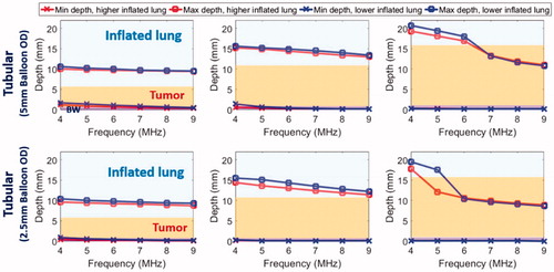
Figure 7. Parametric study of lung flooding: penetration depths (52 °C margin) across frequency of ultrasound applicators with planar (10 mm × 20 mm, red line) or tubular transducers (10 mm balloon OD, blue line) for major airways placement, for treatment of a 2 cm lung tumor located 10 mm (top left) and 20 mm (top right) away from the outer bronchial wall (top row); comparison of deep lung endobronchial tubular ultrasound applicators (5 mm balloon OD, green line and 2.5 mm balloon OD, magenta line) for treatment of a 1 cm lung tumor located 5 mm (bottom left) and 10 mm (bottom right) away from the outer bronchial wall (bottom row). The ablation zone extends between min-depth and max-depth, as depicted. BW – bronchial wall. Min-depths of the tubular applicator with 5 mm balloon OD were overlapped by min-depth of the 2.5 mm balloon OD tubular applicator.
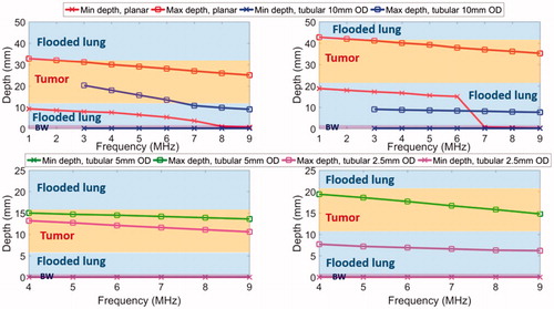
Figure 8. Temperature and thermal dose distributions of patient-specific Model 1 on the coronal (a, b) and axial plane (c, d) after 300 s sonication with an endobronchial ultrasound tubular applicator (6 mm transducer OD × 10 mm length, 10 mm balloon OD, 6 MHz, 9 W/cm2, 120° active zone), as applied to deliver thermal coagulation to the tumor (∼1 cm in depth) attached to major airways. Temperature contours of 45 °C, 50 °C, and 60 °C are shown in (a) and (c), and thermal dose contours of 30 EM43˚C and 240 EM43˚C are shown in (b) and (d). US: ultrasound.
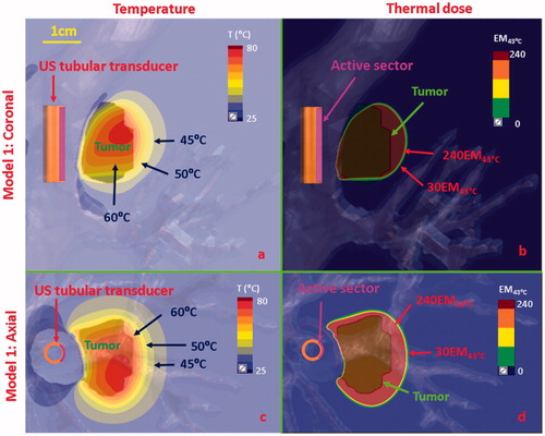
Figure 9. Temperature and thermal dose distributions along the coronal plane obtained after 300 s sonication using endobronchial planar applicators in (a, b) Model 2 representing treatment of a tumor directly attached to the bronchial wall with lower inflated lung, and (c, d) Model 3 representing a tumor separated by 2 cm from the bronchial wall with lung flooding. Two different applicator configurations were applied: 5 MHz, 4.5 W/cm2 for model 2; 3 MHz, 7.5 W/cm2 for Model 3. Temperature contours of 45 °C, 50 °C, 60 °C, and 70 °C are shown in (a) and (c), and thermal dose contours of 30EM43˚C and 240 EM43˚C are shown in (b) and (d). US: ultrasound.
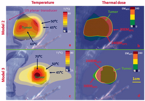
Figure 10. Temperature and thermal dose distributions for patient-specific Model 4 along the coronal (a and b) and axial planes (c and d) after 300 s sonication with an endobronchial tubular applicator (2 mm transducer OD × 10 mm, 150° active zone, 7 MHz, 30 W/cm2) applied to deliver thermal coagulation to the tumor in conjunction with lung flooding. The 2 cm diameter tumor volume is adjacent to and separated by approximately 5 mm of lung from the tertiary bronchial airway in deep lung. Temperature contours of 45 °C, 50 °C, and 60 °C are shown in (a) and (c), and dose contours of 30EM43˚C and 240EM43˚C are shown in (b) and (d). US: ultrasound.
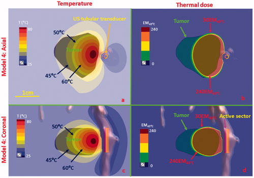
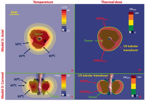
Figure 11. Temperature and thermal dose distributions for patient-specific Model 5 along the axial (a and b) and coronal planes (c and d) after 300 s sonication with an endobronchial tubular applicator (1.7 mm transducer OD × 10 mm, 360° active zone, 7 MHz, 12.5 W/cm2). The 2 cm diameter tumor volume is encompassing and adjacent to the tertiary bronchial airway, surrounding with higher inflated lung. Temperature contours of 45 °C, 50 °C, and 60 °C are shown in (a) and (c), and dose contours of 30EM43˚C and 240EM43˚C are shown in (b) and (d). US: ultrasound.