Figures & data
Figure 1. 2D Finite element simulations of a single-turn induction coil. Computer simulation of magnetic field strength distribution in a single turn induction coil.
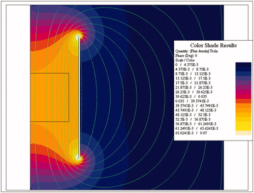
Figure 2. 2D Finite element simulations of a three-piece induction coil set and image of prototype Maxwell inductor. (a) Coil and mesh diagram from 2D FEA for a three-piece induction coil set. (b) Image showing three-piece induction coil set, heat stations, oscilloscope, magnetic field probe and water jacket. (c) Image of the cylinder used for field mapping. Left photograph is the view along the length of the cylinder, and right shows radial view.
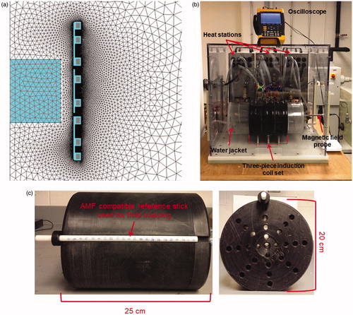
Figure 3. Finite element simulation model of gel phantom. Schematic of the geometric setup, mesh and boundary conditions.
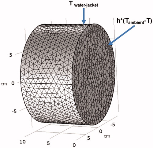
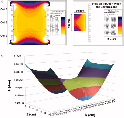
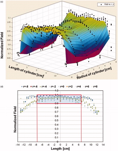
Figure 5. Measured magnetic field generated by Maxwell induction system is uniform. (a) Uniform magnetic field area (cylindrical volume of ∼3.2 × 103 cm3) of ±10% in error margin (in green) at 7.5 kA/m (rms). (b) Uniform magnetic field area (cylindrical volume of ∼2.9 × 103 cm3) of ±10% in error margin (in green) at 10 kA/m (rms). (c) Uniform magnetic field area (cylindrical volume of ∼2.7 × 103 cm3) of ±10% in error margin (in green) at 15 kA/m (rms).
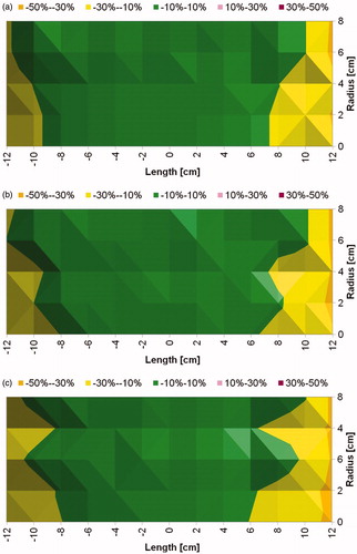
Figure 6. Tests with gel phantoms demonstrate extent of nonspecific heating arising from eddy currents. (a) Schematic of the experimental setup of the tissue equivalent gel phantom exposed to an AMF amplitude of 3 kA/m (rms) generated by the three-piece Maxwell-type induction coil and cooled with water jacket at 20 °C for 20 min. Transient temperature measurements were carried out at six locations (denoted by ‘x’ in the figure) beginning at the gel center (r = 0) and at 1 cm increments toward the outer edge. (b) Temperatures measured in gel phantom with fiber optic probes when exposed to 3 kA/m field. Radial dependence of nonspecific heating in tissue mimicking gel phantom placed inside the circulating water jacket at room temperature is demonstrated. (c) 2D Temperature distribution at the center of the simulation geometry when exposed to an AMF amplitude of 3 kA/m (rms) at 150 kHz for 20 min. The FEA simulations of temperature distribution in gel phantom due to nonspecific heating arising from eddy currents predict similar trends as measured experimentally as shown in (b).
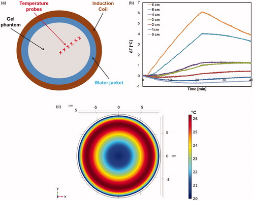
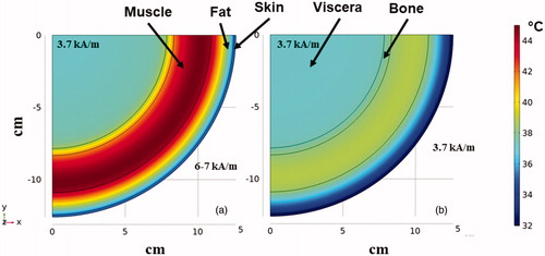
Figure 7. FEA simulations of temperature distribution in the multilayer cylindrical thermal regulatory model comparing nonspecific heating from nonuniform and uniform AMFs. Thermal distribution at the end of 20 min heating time at a fixed frequency of 150 kHz for (a) exposure to inhomogeneous fields as generated by MFH®300F with amplitude of ∼3.7 kA/m at target located ∼12 cm depth. (b) As in (a) but from uniform AMF from the human scale modified Maxwell coil.