
Figures & data
Figure 1. Consort flow diagram of the study.
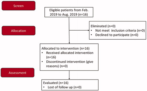
Table 1. Characteristics of the patients and nodules at baseline.
Figure 2. Establishment of neural monitoring system (a) A pair of cutaneous, surface-electrodes were attached to the neck skin of the left and right lamina of the thyroid cartilage (b) Another pair cutaneous surface electrodes were attached to the upper arm of the patient (c) Ambu® Neuroline 715 single patient surface electrodes (d) Nerve stimulation needle was connected to a saline syringe as a stimulating electrode (e) All electrodes were connected an interface-connector box.
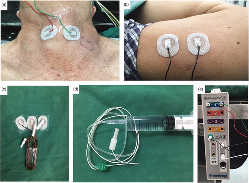
Figure 3. Procedure of neural monitoring during radiofrequency ablation of thyroid nodules (a) An ultrasoundguided puncture with the nerve-stimulation needle was performed between the lateral common carotid artery (CCA) and the medial internal jugular vein (IJV) and the vagus nerve (VN) was identified (b) EMG amplitudes were measured by NIM® Nerve Monitoring System 3⋅0 (Medtronic) (c) The needle was used to inject saline and continuously detect the recurrent laryngeal nerve with 3.0 mA current (d) A ‘liquid isolation zone’ was formed with a width of approximately 5 mm on the dorsal side of thyroid gland (e) The radiofrequency electrodes were placed into the nodule, and ablation was performed (f) After ablation, a final vagus electromyography (V2) was induced using 3.0 mA stimulus current and fibro laryngoscopies were performed on the first day following the procedure.
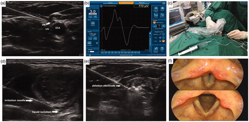
Figure 4. Simulation diagram of main steps (a) Initial Vagal Stimulation (b) Detection of RLN and Hydrodissection Technology (c) US-Guided RF Ablation (d) End of RFA Neural Testing.
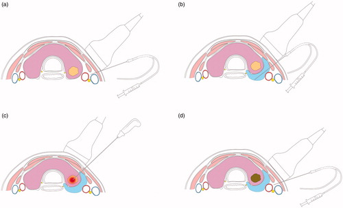
Table 2. Neural monitoring data during ultrasound-guided thyroid nodule ablation.
Table 3. Correlation of electrophysiologic events with RLN function.