Figures & data
Figure 1. Thermobrachytherapy balloon design. The outer balloon is filled with MNP to heat tumor bed and the inner balloon is inflated with saline to expand the resection cavity wall into more advantageous near-spherical geometry. A catheter extends through the flexible shaft and along the outer balloon wall to insert a temperature monitoring and control sensor. A central catheter extends from the surface to the balloon center for inserting an HDR radiation source. Two catheters extend from valved ports to fill the balloons with saline and MNP solution.
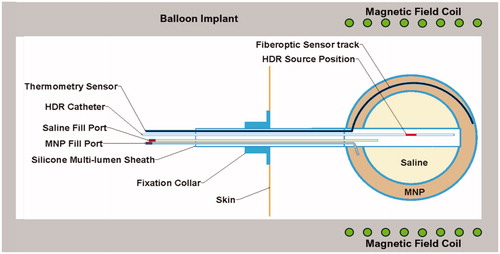
Figure 2. Photograph of laboratory induction heating system used for initial characterization of heating from MNP-filled balloon implants, including radiofrequency power amplifier, matching network and water-cooled 26 × 31 × 20 cm3 head coil (AMF Life Systems, Auburn Hills MI).
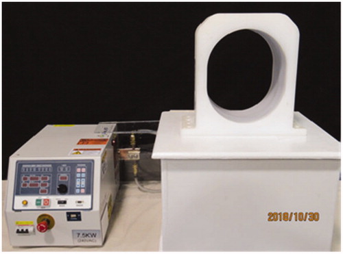
Figure 3. Experimental setup of magnetic nanoparticle (MNP) balloon implant heating: (A) 2-cm diameter MNP-filled balloon buried 4-cm deep in the central plane of a split-apart human skull model that is filled with brain tissue-equivalent phantom and 2.5-mm spaced thermocouples to measure radial penetration of heating. (B) Split-apart skull/brain model assembled inside the head coil for application of radiofrequency magnetic field.
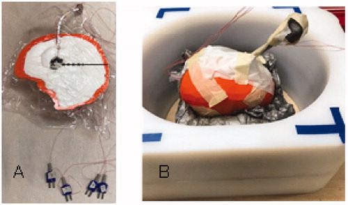
Table 1. Thermal and physiological properties used in the numerical simulations [Citation37].
Table 2. Mesh settings that yield a mesh-independent solution.
Figure 4. Magnetic field profiles in head coil. (A) Magnetic field as a function of position along the coil axis in the center (blue) and two positions along the outer casing of coil. (B) Magnetic field profiles horizontally and vertically across the coil at coil center (solid) and at each end of coil (dash).
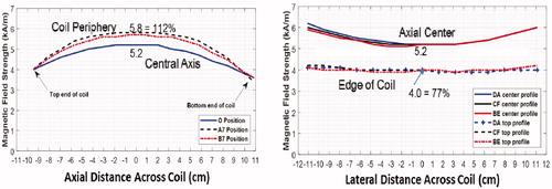
Figure 5. Reproducibility of nanoparticle heating. (A) Heating rate of 2-cm diameter MNP-filled GliaSite® balloon in air obtained during nine independent trials at three different field strengths. (B) Power absorption in equal volume MNP-filled test chambers immersed in different magnetic field strengths repeatedly over a period of 5 months, fitted to the expected magnetic field-squared relationship (solid line).
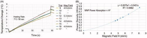
Figure 6. Temperature rise of the MNP filled balloon surface and at 2.5, 5, 7.5, 10 and 12.5 mm radial distance in brain tissue-equivalent phantom.
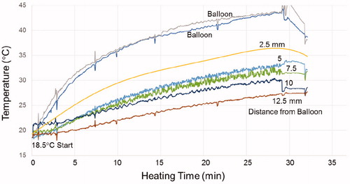
Figure 7. (A) Human skull split-apart model filled with gelled brain tissue-equivalent phantom and 2-cm diameter magnetic nanoparticle filled balloon. (B) Thermographic camera image of the head phantom central cross-section after immersion in a magnetic field for 20 min. (C) Temperature profiles along the four radial cross-sections marked on demonstrate the symmetry of heating around the nanoparticle filled balloon.
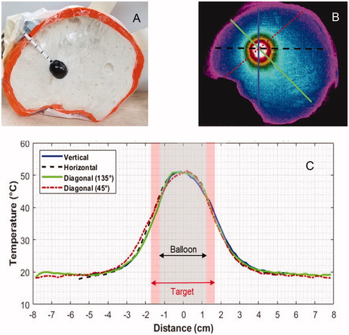
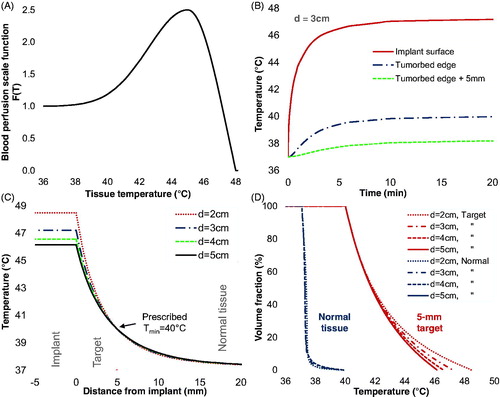
Figure 8. Numerical simulations of MNP balloon implant heating. (A) Temperature-dependent blood perfusion scaling function F(T); (B) Simulated temperature as a function of time at the implant surface and radially 5-mm (tumor edge) and 10-mm from the surface of a 3-cm diameter balloon; (C) Simulated temperatures around 2, 3, 4, and 5 cm diameter TBT balloons implanted in tumor resection cavities in well-perfused white matter. (D) Simulated cumulative temperature-volume histograms for 2, 3, 4, and 5 cm diameter balloons heating a 5-mm annular rim target of perfused white matter. Note that for all size balloons, 100% of the 5-mm annular tumor bed target is heated above 40 °C and about 50% of the target volume is heated above 41.8 °C for balloon surface temperatures of 46.2–48.5 °C.