Figures & data
Table 1. Ablation parameters and volumes.
Figure 1. Robotic manipulator positioned near the MR scanner.
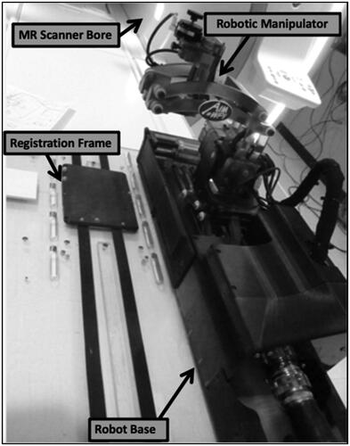
Figure 2. Clinical workflow of MRgRA delivery of NBTU. Top, left – a burr hole craniotomy is performed to gain access to the intra-cranial space. Top, middle – the Entry Point and Target Point are selected using our TheraVision software (Acoustic MedSystems, Inc., Savoy, IL, USA) and the coordinates are sent to the robot. Top, right – the robot moves into position and the cannula and ACOUSTx® NBTU applicator (Acoustic MedSystems, Inc., Savoy, IL, USA) are mounted to the robot. The robot then inserts the probe to target depth. Bottom, right – the ablation ensues and thermal changes are monitored using MRTI. Bottom, middle – post operative MRI images are obtained. Bottom, left – the brain is dissected and histologic analysis is performed using TTC staining. The area of damage is calculated using ImageJ (NIH funded open access software).
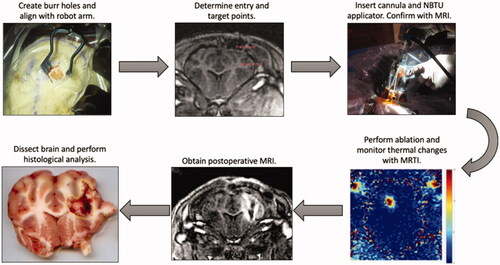
Figure 3. MRTI temperature maps from one acute swine (a) MRI image showing probe location after insertion into swine’s brain. Orthogonal, contiguous MRTI slice placement is shown with shaded blue background indicating the volume of tissue being imaged. (b, top) MRTI maps for slices labeled in (a) set to the maximum heating timepoint. (b, bottom) Improved MRTI software user interface with real-time average temperature plot for a user-drawn ROI in MRTI map.
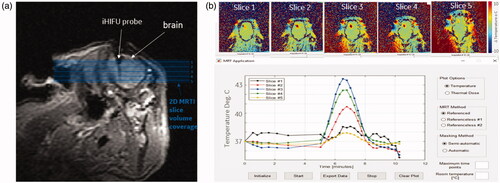
Figure 4. CEM43 dose maps. Left – Pixel grid of CEM43 dose delivered via NBTU. Right – CEM43 isodose lines derived from the pixel grid. The volume of the necrotic zones was calculated by counting the pixels at the specified CEM43 threshold and multiplying by the 3 pixel dimensions.
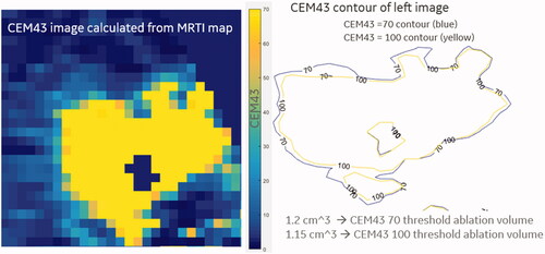
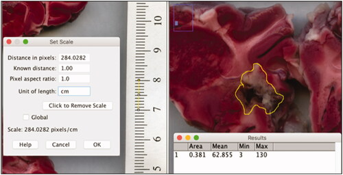
Figure 5. The ablation volume is calculated using ImageJ (NIH funded open access software). Left – a ruler adjacent to the coronal brain sections is used to calibrate the software between pixels and cm. Right – the area of ablation damage is outlined and the software calculates the circled area.