
Figures & data
Figure 1. Sealing mechanism of an RF electrode used as hemostatic device during surgery. The electrode is placed on the bleeding point (A) and the applied RF current creates a coagulation zone that involves shrinkage of the tissue and vessel sealing (B). In the context of surgical oncology, RF-based hemostatic devices can also be used to ablate the surface of the remnant organ to increase the tumor-free margin and minimize local recurrence (C).
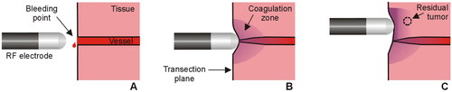
Figure 2. RF-based electrodes for surgical sealing (ex vivo set up). (A) Aquamantys® device (Medtronic, Portsmouth, NH) based on two externally cooled (irrigated) electrodes. (B) Coolingbis® device (Vecmedical, Barcelona, Spain) based on an internally-cooled monopolar electrode. Both devices can create coagulation zones either by moving the device over the tissue (‘painting motion’) or by keeping it fixed on a bleeding point, as shown in . In the first case, RF power was applied with the device slightly inclined to the tissue surface in a continuous circular motion (2.5 cm diameter, ∼1 turn/s) (see yellow arrows).
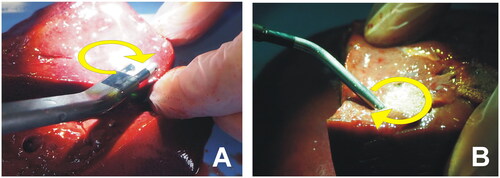
Figure 3. Examples of coagulations zones created with the Coolingbis® device on ex vivo samples. (A) Top view of the tissue surface (i.e., transection plane) showing circular coagulations zones created after moving the electrode during RF application. Only the whitish zone was considered in the measurement of the size, discarding the red margin. (B) Side view of the cut tissue. Depth was measured from the tissue surface.
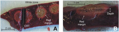
Figure 4. In-silico modeling of the Aquamantys device. (A) Geometry of the ¼ scale 3D model using two symmetry planes. (B) Electrical power density (in W/m3) deposited in saline and tissue at 20 W power.
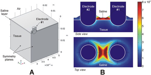
Table 1. Characteristics of the coagulations created ex vivo with the Coolingbis® device (3 mm electrode) in ‘painting motion’ mode (n = 5 applications per level power).
Table 2. Characteristics of the coagulations created ex vivo with the Coolingbis® device (5 mm electrode) in ‘painting motion’ mode (n = 5 applications per level power).
Table 3. Characteristics of the coagulations created ex vivo with the Aquamantys® device in ‘painting motion’ mode (n = 5 applications per level power).
Figure 5. Applied power (blue) and coagulation zone depths (red) created by the Coolingbis® and Aquamantys® devices on ex vivo pig liver in ‘painting’ application mode. In the case of the Colingbis® device the applied power is impedance-dependent, for which the applied power is also plotted. The data (mean and standard deviation) are from .
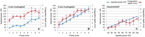
Figure 6. Coagulation zone depths created with the Coolingbis® and Aquamantys® devices on ex vivo (A) and in vivo (B) pig liver in spot application mode. The three power levels are 20, 25 and 30 W in the Aquamantys® device, and a variable and impedance-dependent power level in the Colingbis® (see details in and ).
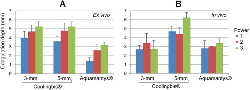
Table 4. Characteristics of the coagulation zones created ex vivo with the Coolingbis® devices (models 3 and 5 mm) and Aquamantys® in spot application mode (n = 5 applications per level power).
Table 5. Characteristics of the coagulation zones created in vivo with the Coolingbis® devices (models 3 and 5 mm) and Aquamantys® in spot application mode (n = 5 applications per level power).
Figure 7. Histological findings from the in vivo coagulation zones created with the 3-mm Coolingbis® (1(A–D)), 5-mm Coolingbis® (2(A–D)) and Aquamantys® (3)A–D)) devices in spot mode.
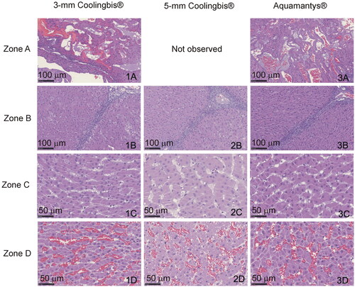
Figure 8. Comparison between macroscopic (top) and microscopic (bottom) samples from the in vivo coagulation zones created with the 3-mm Coolingbis®, 5-mm Coolingbis® and Aquamantys® devices in spot mode.
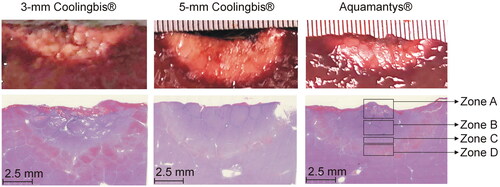
Table 6. Linear regression equations between coagulation depth (D) and applied power (P) with the 3 and 5 mm Coolingbis® and Aquamantys® in spot application mode.
Data availability statement
The data underlying this article will be shared on reasonable request to the corresponding author.