
Figures & data
Figure 1. Research flowchart.
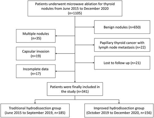
Figure 2. Schematic drawing of the main structures around the thyroid at different cervical levels and hydrodissected fascial spaces. (A) Hydrodissected spaces at the C4-5 level. The infrahyoid muscles could be protected by hydrodissecting the ACS (1). The SLN (green circle and arrowhead) could be protected by the hydrodissected VS (2). The carotid sheath and surrounding muscles could be protected by the POTS (3), isolating fluid. (B) Hydrodissected spaces at the C6 level. The RLN (yellow circle and black arrowhead) could be protected by hydrodissected VS. Hydrodissection was restricted by the suspensory ligament of the thyroid gland (red arrowhead). The trachea could be protected by the hydrodissected VS. (C) The hydrodissected spaces at the C7 level. RLN (yellow circle, black arrowhead) could be protected by hydrodissected VS. (D) Hydrodissected spaces below the C7 level. The RLN (yellow circle and black arrowhead) could be protected by the hydrodissected VS.
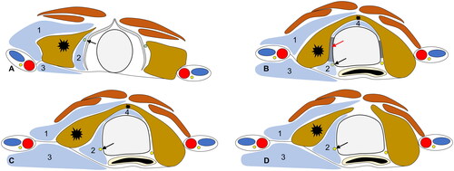
Figure 3. US images of traditional hydrodissection and improved hydrodissection. (A) Traditional hydrodissection before ablation. The strap muscles were swollen (white arrow), and a mixed echoic isolating band formed in this situation; the thyroid and anterior muscle were not effectively separated. (B) Improved hydrodissection in the ACS. The isolating fluid formed an anechoic isolating band (white arrow) and separated the strap muscles, effectively limiting the heat within the thyroid capsule. (C) Traditional hydrodissection before ablation. The hydrodissection area was filled with swollen soft tissue (white arrow). (D) Improved hydrodissection at the VS and POTS. The isolating fluid formed an anechoic isolating band (white arrow) and separated the muscles and trachea.
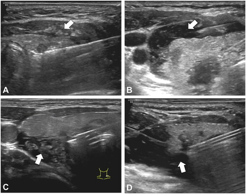
Figure 4. (A–G) US images of improved hydrodissection, as well as a schematic diagram of target nodules (white arrow) at different locations. The ACS hydrodissection (black arrow), VS hydrodissection (white arrowhead), and post-thyroid hydrodissection (black arrowhead) are shown as hypoechoic or mixed echoic bands on the images. The flow directions of the isolating fluid are shown as white thin arrows.
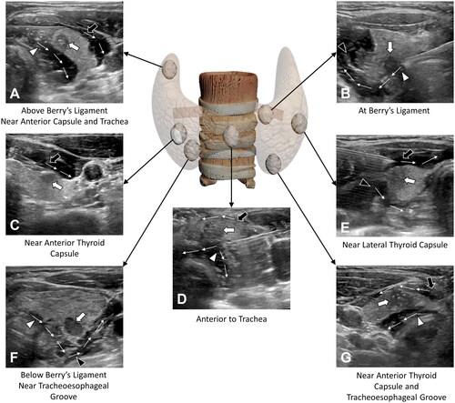
Table 1. Baseline characteristics of the enrolled patients.
Table 2. Hydrodissection strategies according to the location of the thyroid nodule.
Data availability statement
The datasets used and/or analyzed during the current study are available from the corresponding author on reasonable request.