
Figures & data
Figure 1. Flow chart of the patient selection process.
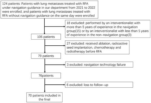
Table 1. Statistics of lesion location.
Table 2. Surgical inclusion and exclusion criteria.
Figure 2. Female patient 66 with bilateral lung metastases after rectal cancer surgery (arrow).
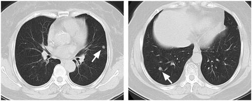
Figure 3. ( A) Position layout of the optical navigation system in the CT room. (B,C) With the assistance of optical and electromagnetic navigation, the interventional doctor performed the puncture operation. The virtual real-time 3D monitoring display screen of the (D) navigation system can simulate the specific position of the probe.
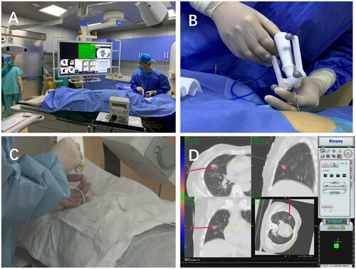
Figure 4. Radiofrequency electrode needles were implanted under CT monitoring (thin arrow) according to different positions of the lesions. A thousand leaf needle was placed near the pleura to continuously infusion 5% lidocaine to maintain anesthesia (thick arrow). After ablation, a halo sign was observed around the lesions.
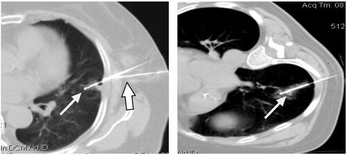
Figure 5. Female patient 66, postoperative rectal cancer, CT review 1 month after ablation, the ablation area showed triangular and cord-like consolidation without significant enhancement (arrow).
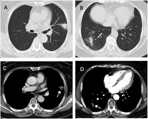
Table 3. Results of procedure time, procedure time, and ablation time for each group.
Table 4. Complications in each group.
Table 5. Results of postoperative follow-up in each group.
Data availability statement
The data used to support the findings of this study are available from the corresponding author upon request. The authors will provide the original data without reservation.