Figures & data
Figure 1. Dimensions of the specimens.
Table 1. Chemical composition of base metal and filler metal (wt-%).
Figure 2. Schematic of the GMAW with LUIT. (a) Filling the groove to a certain height; (b) UIT on the weld metal; (c) continuing bead deposition; (d) UIT on the newly deposited beads; (e) welding and UIT alternately until the groove is fully filled and final UIT on the weld toe and weld cap.
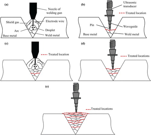
Table 2. Welding parameters.
Figure 3. Weld profiles and welding sequences. (a) Weld profile of the conventional welding specimen; (b) weld profile of the LUIT-processed specimen; (c) welding sequence of the conventional welding specimen; (d) welding sequence of the LUIT-processed specimen (scales visible in (a) and (b) are in cm).
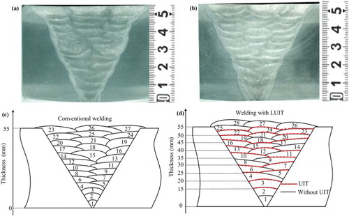
Figure 4. Appearance of a weld surface after UIT.
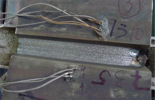
Figure 5. Schematic of the cut planes.
Figure 6. Schematic of clamping arrangement for the EDM cut.
Figure 7. Comparison between the microstructures in the weld zones of the two specimens. (a) Pass 3 in the conventional welding specimen; (b) the intersection zone between pass 2 and pass 3 in the conventional welding specimen; (c) pass 2 in the conventional welding specimen; (d) pass 3 in the LUIT-processed specimen; (e) the beads intersection zone between pass 2 and pass 3 in the LUIT-processed specimen; (f) pass 3 in the LUIT-processed specimen.
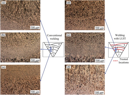
Figure 8. Microstructures at different locations in the LUIT-processed weld. (a) Pass 23 deposited on UIT surface; (b) pass 20 deposited on un-treated surface; (c) pass 14 deposited on UIT surface; (d) pass 20 deposited on UIT surface; (e) pass 20 deposited on UIT surface and base metal; (f) pass 17 deposited on un-treated surface and base metal.
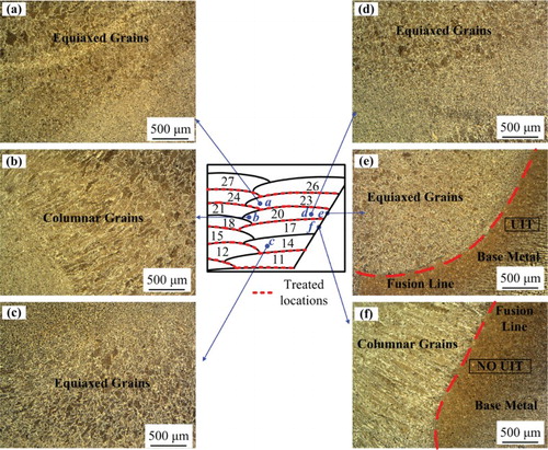
Figure 9. Hardness distributions on the cross-section (dimensions in mm).
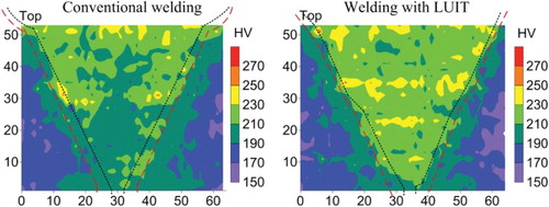
Figure 10. Residual stress distributions measured with CM. (a) Conventional weld joint; (b) LUIT-processed joint.
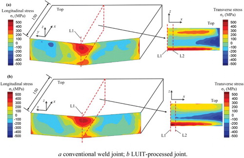
Figure 11. Through thickness stress distribution at the weld centreline. (a) Longitudinal stress; (b) transverse stress.