Figures & data
Table 1. Chemical compositions of the quench-and-tempered bearing steels used for model development. The asterisk (*) represents the initial carbon content before carburisation. is shown beside the carbon content, and iron forms the balance of the respective compositions.
Table 2. List of symbols in the present work.
Table 3. Model parameters for the implementation of Equation (7). Steel designations are included next to the values of and
.
Table 4. Model parameters for the implementation of Equation (11).
Table 5. The measured and calculated for the quench-and-tempered steels.
Table 6. Material parameters, measured and calculated for steels with alternative microstructures.
Figure 1. Measured and calculated retained volume fraction () of steels with quench-and-tempered microstructure.
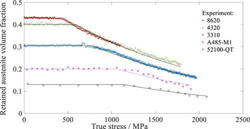
Figure 2. Measured and calculated retained austenite volume fraction () of bainitic, QP and TRIP steels. The transformation curves are shown in separate plots for clarity.
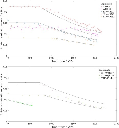
Figure 3. The change in critical stress as a function of (a) solute concentration; (b) temperature; (c)
.
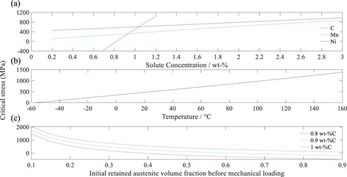
Figure 4. (a) Required manganese and nickel concentrations for a range of critical stresses at a deformation temperature of 20°C and of 0.43; (b) change in retained austenite volume fraction
with applied stress for selected compositions.
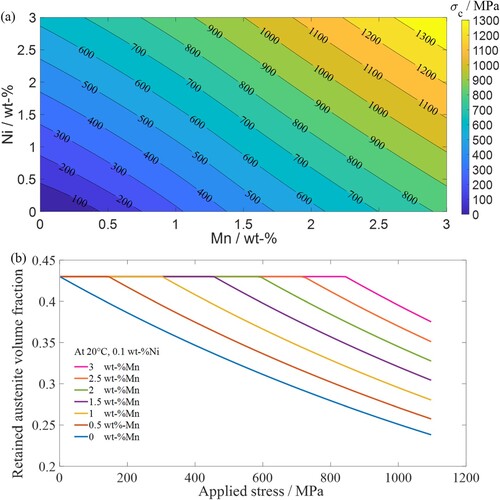
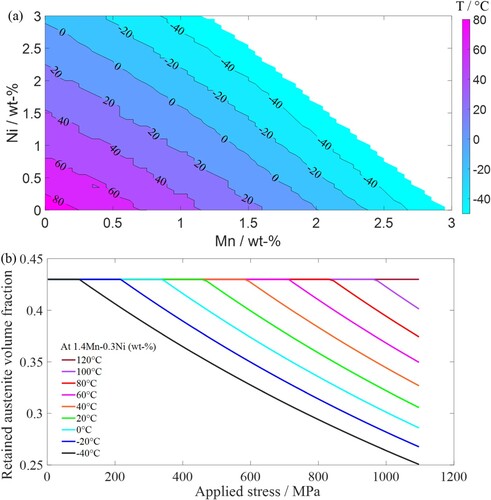
Figure 5. (a) Required manganese and nickel concentrations for deformation temperatures between −50°C and 80°C with values within a range of 400–500 MPa; (b) change in retained austenite volume fraction
with applied stress for a composition of 1.4Mn-0.3Ni (wt-%) within a temperature range of −40°C to 120°C.