Figures & data
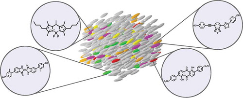
Figure 1. (colour online) Schematic diagram of an alignment guest–host system showing the absorbance of light perpendicular to the director, n, and the transmittance of light parallel to the director.
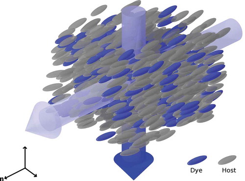
Figure 2. (colour online) Schematic representation of a double layer guest–host display in the absorbing ‘off’ state (left) and in the transmitting ‘on’ state (right).
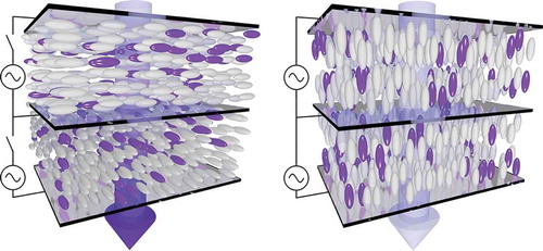
Figure 3. (colour online) Schematic diagram of the experimental set-up for measuring the polarised absorbance of an aligned guest–host sample.
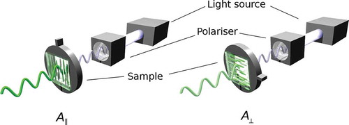
Figure 4. Structure and atom numbering of the anthraquinone chromophore.
Table 1. Examples of structures from different dye classes proposed for use in guest–host systems, along with typical reported properties in nematic hosts.
Figure 5. Examples of structures from different dye classes proposed for use in liquid crystal lasers.
Figure 6. Examples of benzothiadiazole (top), anthraquinone (middle) and indigo (bottom) dye structures that exhibit thermotropic liquid crystal phases (SmA = smectic A, SmC = smectic C, N = nematic).
Figure 7. (colour online) Schematic visualisation of the orientations of the host molecules (green) the dye molecules (blue) and the transition dipole moments of the dyes (red) in a guest–host system relative to the director, n.
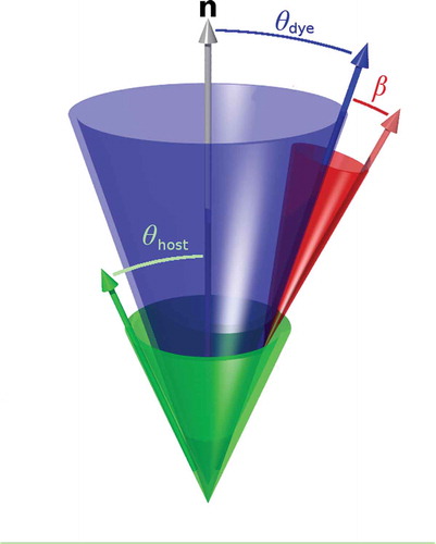
Figure 8. Two 1,5-diamine substituted anthraquinone dye structures and their order parameters in a nematic host.[Citation78].
![Figure 8. Two 1,5-diamine substituted anthraquinone dye structures and their order parameters in a nematic host.[Citation78].](/cms/asset/987a7d9d-81e6-4b86-b583-82b26d1f86c6/tlct_a_1189613_f0008_b.gif)
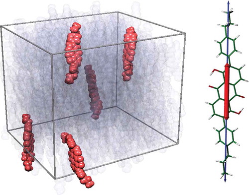
Figure 9. (colour online) A snapshot of a liquid crystal guest–host MD simulation (left) showing the dye molecules in orange and the host molecules in translucent grey. The visible TDM (red) and long molecular axis (blue) are also shown overlaid on the DFT-optimised structure of the dye (right).