
Figures & data
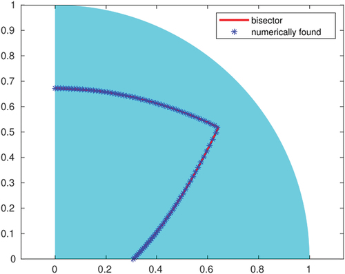
Figure 1. AFM image of families of oily streaks of 8CB on substrate. Reprinted with permission from [Citation1] (copyright 2014, American Physical Society).
![Figure 1. AFM image of families of oily streaks of 8CB on MoS2 substrate. Reprinted with permission from [Citation1] (copyright 2014, American Physical Society).](/cms/asset/9d1c0134-fe9f-467d-bee1-a8cce79d0d4d/tlct_a_2192183_f0001_b.gif)
Figure 2. (Colour online) Experimental representation of cross-sectional layer configuration in an oily streak of 8CB on PVA substrate. Reproduced from [Citation5] with permission from the Royal Society of Chemistry.
![Figure 2. (Colour online) Experimental representation of cross-sectional layer configuration in an oily streak of 8CB on PVA substrate. Reproduced from [Citation5] with permission from the Royal Society of Chemistry.](/cms/asset/61de3218-bd32-4ddd-a962-0100ee8caf41/tlct_a_2192183_f0002_oc.jpg)
Figure 3. (Colour online) Left: given + and
–, there are four unit vectors
,
,
,
that satisfy (10). The
-tensors
+ and
– are represented by (arrowless black) straight lines, oriented parallel to the molecular directors
+,
– corresponding to
+,
– respectively. Here
+ and
+ (respectively,
– and
–) are related to each other by (5). Centre and right: two piecewise constant configurations that satisfy (10). The black lines represent the smectic layers, which are orthogonal to the molecular director, and the thick red line represents the jump.
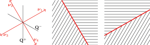
Figure 4. (Colour online) A mathematical pathology associated with the energy density , given by (12). The black lines represent the smectic layers, while the thick red line represents the jump set. On the left, a piecewise constant configuration in a rectangle, with a zig-zag interface and zig-zag angles of
degrees; on the right, a piecewise constant configuration with a horizontal jump set. If we choose the energy density as in (12), the energy of the configuration on the left is
, where
is the length of the bottom base of the rectangle, irrespective of the spacing of the zig-zag. As the latter tends to zero, the configuration on the left converges (in a suitable sense) to that on the right, which costs an infinite energy.
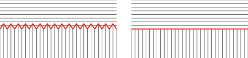
Figure 5. (Colour online) The domain and boundary conditions in the definition of BV-ellipticity (Definition 2.1). The domain is a unit square, rotated in such a way that the sides are parallel to
,
. The ‘boundary conditions’, defined in a collar of
, are piecewise constant and are defined by
+ and
–. The admissible configurations
are piecewise constant inside
(and are allowed to take finitely many values only).
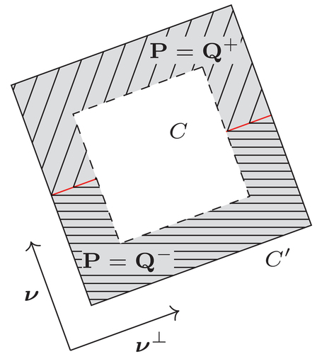
Figure 6. (Colour online) The minimizing configuration given by Proposition 3.2. The black lines represent the smectic layers, while the thick red line is the jump set .
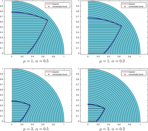
Figure 7. (Colour online) Numerics for the problem on a quarter circle. All the pictures have .
Data availability statement
Data sharing is not applicable to this article as no new data were created or analysed in this study.