
Figures & data
Figure 1. Schematic showing the low-cost cornea bioprinting process. A digital corneal model was derived from patient data and was used for generating CAD models of both corneal scaffolds and support molds. A modified desktop 3D printer was used to print cornea structures with the aid of the support mold. A mold holder was used in conjunction with a custom start G-code to facilitate the initial positioning.
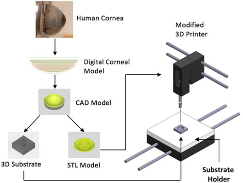
Figure 2. Digital corneal models with (0,0) as center, x is distance from the center, and y is through-thickness depth relative to plane at apex. (A) Cloud point curves defining the meridian section of corneal models with different radii of curvature. Data were derived from the original corneal model. 3D corneal models created from the cloud point data in (A), with model configurations matching (B) human average values, (C) human lower bound values (steep), and (D) upper bound values (flat), of the human cornea radii of curvature.
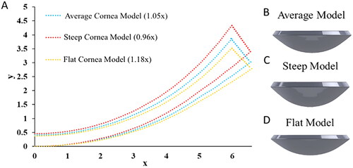
Figure 3. Low-cost cornea bioprinting setup. (A) Modified 3D printer. (B) Syringe-based extruder assembled from 3D-printed parts. (C) A 3D-printed concave substrate. (D) A 3D-printed convex substrate.
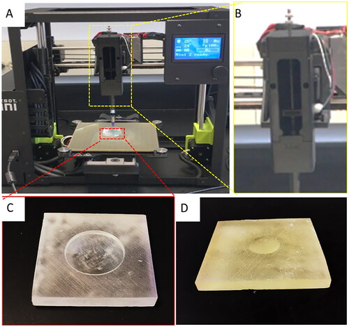
Table 1. Compilation of costs associated with graft production.
Figure 4. Comparison of optical properties of the corneal structures printed with the modified FRESH process and the standard bioprinting method. (A) FRESH printed corneal structures showing well preserved cornea shape. (B-C) Overview and microscopic images of FRESH printed corneal structures with a collagen-based bioink. (D-E) Overview and microscopic images of FRESH printed corneal structures with an alginate-based bioink. (F) Corneal structures printed with the standard (presented) bioprinting method.
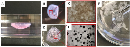
Figure 5. 3D structure of bioprinted corneal scaffolds and their optical properties. (A-C) Top, bottom and section view of the printed corneal structure. (D-E) The printed corneal structures were exposed to green (540 nm) and blue (480 nm) fluorescent illumination, showing overall dome shape. (F-G) Depiction of transparency of the printed corneal structures in liquid and air, respectively.
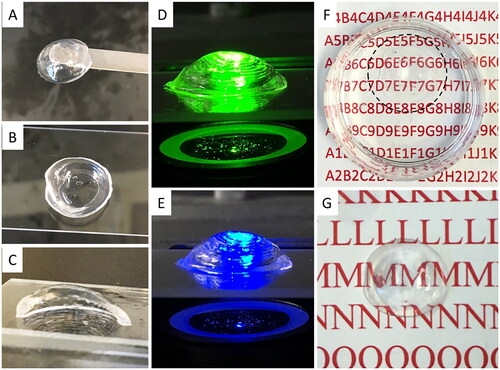
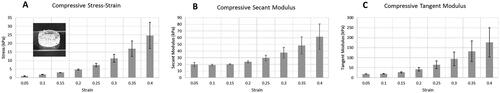
Figure 6. Mechanical properties of the printed structures. (A) Compressive stress-strain results of a 3D printed cylindrical test coupon (shown in the inset). (B) Compressive secant modulus of the test coupon. (C) Compressive tangent modulus of the test coupon. Error bars represent standard deviations for 3 experimental replicates.
Data availability statement
All data supporting the findings of this study are available from the corresponding author, Katelyn E. Swindle-Reilly, upon request.