Figures & data
FIGURE 1 Representative anterior and lateral teeth of Isurus species included in this study. For each figure portion, teeth in the top row are from the upper jaw and the bottom row from the lower jaw. Scale bar = 1.0 cm. A, I. oxyrinchus, labial view (Florida Museum of Natural History 030102013.28); B, I. paucus, labial view (GHC LONG1786); C, Isurus hastalis, lingual view (USNM 453155, 474480, 474986, 474988); D, I. xiphodon, lingual view (USNM 421913, 278765, 421916, 482217).
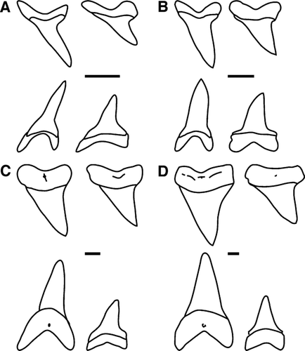
TABLE 1 Specimens used in morphometric analysis. : , Calvert Marine Museum; , Field Museum of Natural History; , Private collection of Gordon Hubbell; , Kwa-Zulu Natal Sharks Board; , United States National Museum of Natural History; , information not available; , female; , male.
FIGURE 2 Location of landmarks for geometric morphometric analysis. 1, cusp apex; 2, center of the inner edge of the root; 3, 4, junction of cusp edge and root; 5, maximum curvature of root center; 6, 7 apex of root lobe.
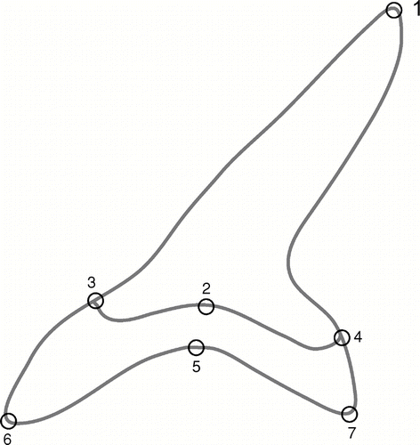
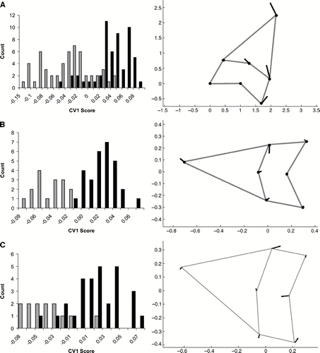
FIGURE 3 Canonical variates analysis of Procrustes landmarks for I. oxyrinchus and I. paucus. Histograms on the left side of the figure are counts of CV1 scores. Black bars equal I. oxyrinchus; grey bars equal I. paucus. Vector plots on the right show the variation represented on CV1 as values become more positive. A, all tooth positions; B, anterior teeth only (positions 1 and 2); C, lateral teeth only (positions 4 through 7).
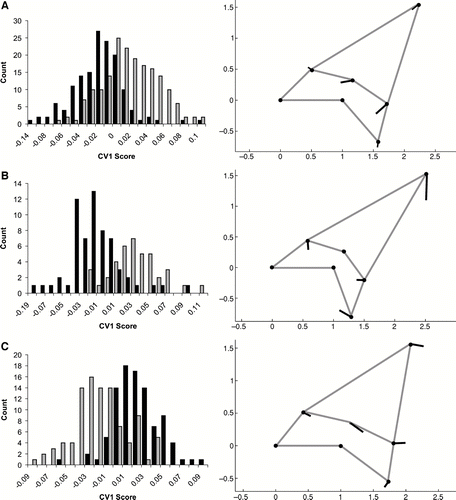
FIGURE 4 Canonical variates analysis of Procrustes landmarks for I. hastalis and I. xiphodon. Histograms on the left side of the figure are counts of CV1 scores. Black bars equal I. hastalis; Grey bars equal I. xiphodon. Vector plots on the right show the variation represented on CV1 as values become more positive. A, all tooth positions; B, anterior teeth only (positions 1 and 2); C, lateral teeth only (positions 4 through 7).