Figures & data
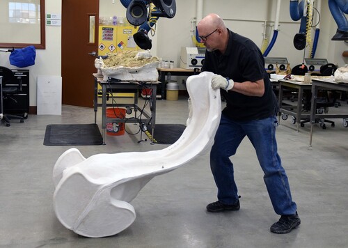
FIGURE 1. A closed and opened clamshell storage jacket for the skull of LACM 150150, the type specimen of the desmostylian Neoparadoxia cecilialina, at the Natural History Museum of Los Angeles County (LACM).
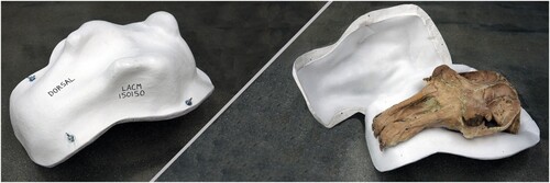
FIGURE 2. LACM 150150 being A, cleaned and B, conserved before the jacketing process begins.
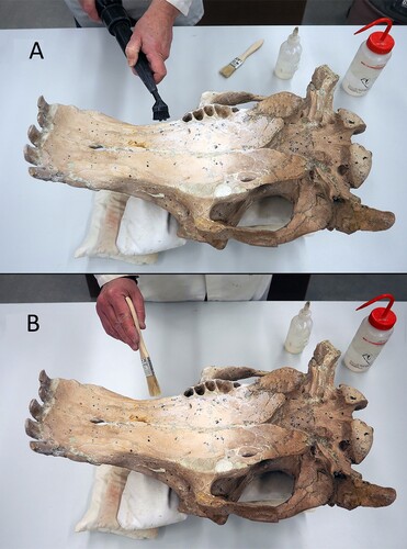
FIGURE 3. Midline of the LACM 150150 skull where the two sides of the clamshell will meet, based on the skull's morphology and robustness.
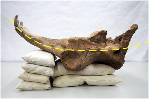
FIGURE 4. LACM 150150, A, being embedded in the sandbox to create the dividing line on the skull and, B, the margin leveled to support the flange.
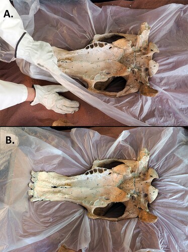
FIGURE 5. Creating voids, A, around a delicate process and, B, around a tooth using clay; C, fragile parts of the skull padded with clay and foam to avoid contact with the jacket.
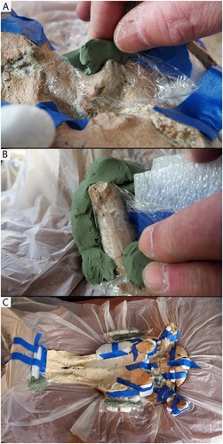
FIGURE 6. The lining material has been laid over the specimen and set in place with sandbags, and locations for darts are being determined and created.
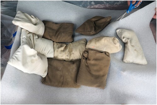
FIGURE 7. The sequence to create a welded dart is to, A, cut along the fold in the liner, shield the specimen under the area to be welded with aluminum foil, B, overlap and heat both contact surfaces simultaneously with a heat gun until they are tacky, and press them together. This technique takes some practice but is the quickest and most archival method of binding a dart.
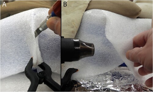
FIGURE 8. The sequence to create a sewn dart is: A, cut the liner to where the crease begins; B, overlap the sides, mark the seam line along the cut edge, and draw hash marks across that edge; C, cut the resulting wedge out of the bottom section of the overlap; D and E, line up the hash marks and stitch the seam together with polyester thread.
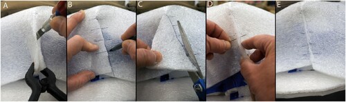
FIGURE 9. The locations and shapes of the jacket feet have been determined, carved out of foam, and placed where they will reside on the jacket. They will be removed and set aside for later inclusion.
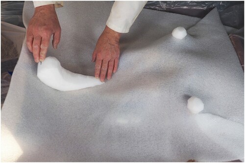
FIGURE 10. A hand grip that was carved out of poly-foam and plastered onto the flange of a large jacket.
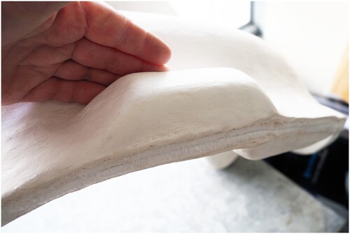
FIGURE 11. The first layers of plaster and fiberglass being applied to the darted liner resting on the specimen.
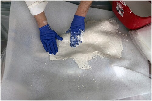
FIGURE 12. The first three layers of plaster and fiberglass have been applied to the skull of LACM 150150, covered with plastic, and weighed down with sandbags to force the poly-foam liner to conform to the bone until the plaster sets.
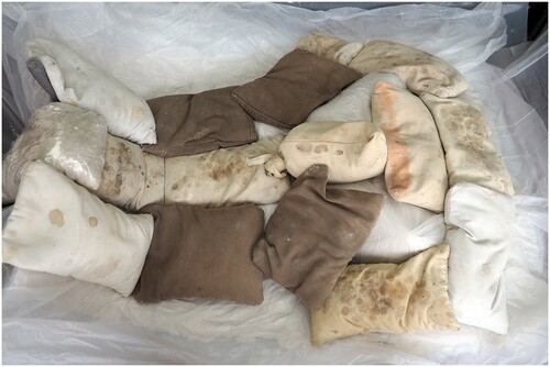
FIGURE 13. The feet have been plastered in place on the jacket, and the plaster surface is being smoothed before setting.
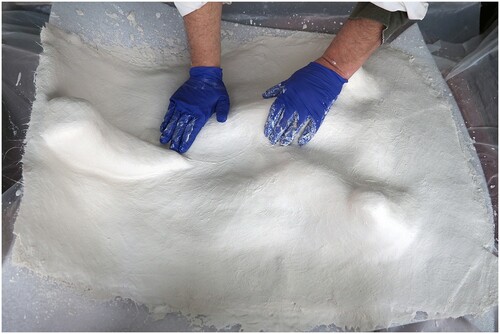
FIGURE 14. Once the first side of the jacket is dry, A, the flange is marked about 75 mm (or four finger widths) from the specimen. Then the specimen is set aside and, B, the flange is trimmed with an oscillating saw.
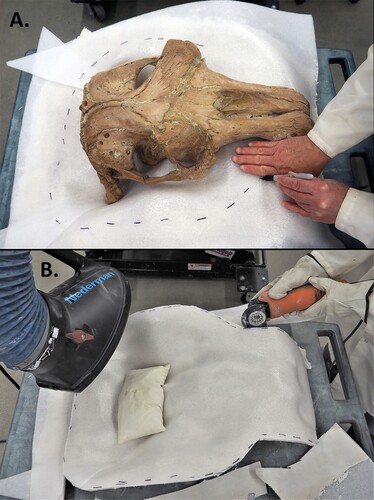
FIGURE 15. LACM 150150 returned to the first side of its jacket and readied for construction of the second side.
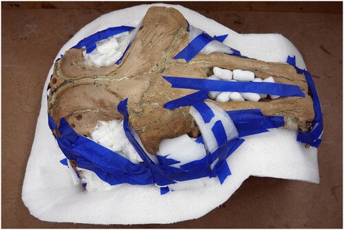
FIGURE 16. The poly-foam liner for the second side has been made and is being held in place with sandbags. Note that the liner does not extend across the flange.
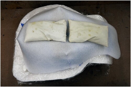
FIGURE 17. The specimen was removed from the finished clamshell jacket and set aside while holes were drilled through the jacket flange. Bolts have been installed and the second side is being trimmed and smoothed to match the first side.
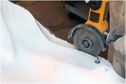
FIGURE 18. Bolt the two sides together, arranging the hardware in the following order: bolt/screw head—washer—flange—washer—wingnut. The bolts should be snugly tightened, but not overtight.
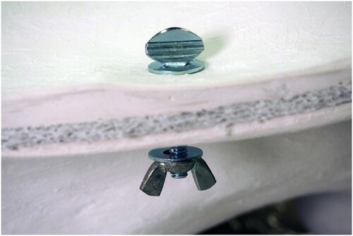
FIGURE 19. The completed jacket of LACM 150150 resting safely in the collections.
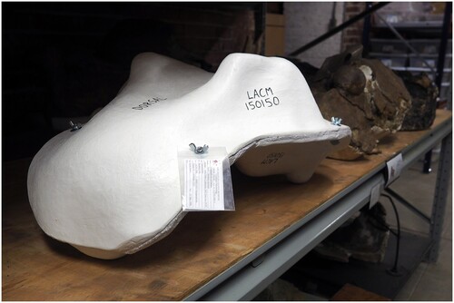
FIGURE 20. Rockers can be added to the heavy side of large jackets to aid in flipping the specimen over to examine its opposite side. Shown: clamshell jacket for the skull of LACM (CIT) 106/14, Mammuthus exilis, with rockers to aid in flipping the specimen over. (Photo by Stephanie Abramowicz)
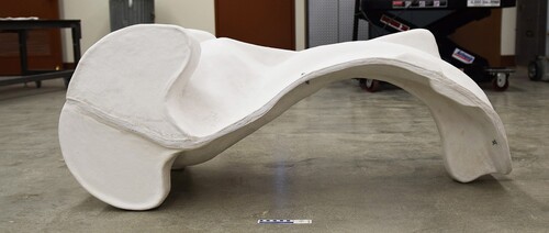
FIGURE 21. Specimens too large for a sandbox must have their flange surfaces made a different way. Here, scrap foam core has been cut and stacked around the skull of LACM (CIT) 106/14 to create the flange surface along the dividing line.
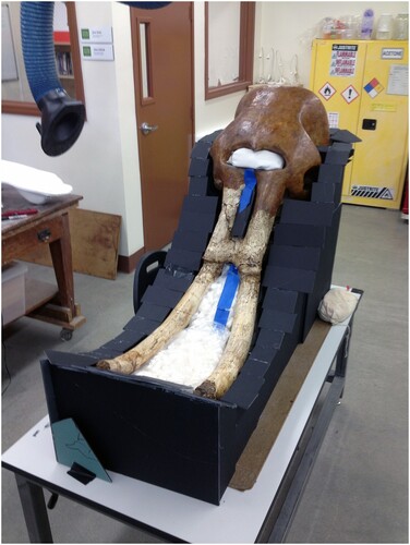
FIGURE 22. The rockers on this jacket extend 12 mm beyond the flange in order to protect the flange while flipping the jacketed specimen.
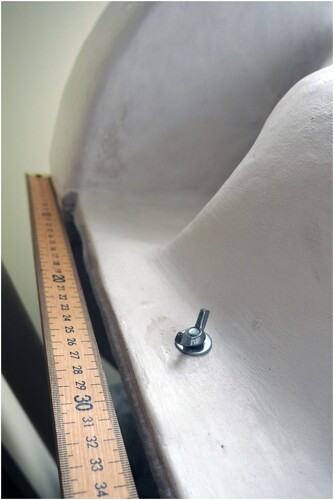
FIGURE 23. AWZ demonstrating how a single person can flip the clamshell jacket with rockers containing the skull of LACM (CIT) 106/14. (Photo by Stephanie Abramowicz)