Figures & data
FIGURE 1. Photograph of a lean Lake Trout undergoing electrosedation with a Portable Electrosedation System unit (Smith-Root, Inc.; A = power supply box; B = exposure chamber).
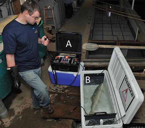
FIGURE 2. Illustrations of three different types of DC produced by the Portable Electrosedation System unit (Smith-Root, Inc.): (A) continuous DC, in which voltage increases from zero to a maximum programmed voltage level within 1 s and decreases to zero 1 s after a predetermined exposure duration; (B) pulsed DC, in which voltage begins at the maximum programmed voltage, stays constant for the entire pulse duration, and then drops to zero; and (C) dual-frequency pulsed DC, characterized by bursts of brief pulses at high frequency, with each burst delivered at low frequency.
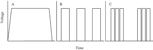
TABLE 1. Descriptions of four Portable Electrosedation System unit (Smith-Root, Inc.) settings that were used to electrosedate lean Lake Trout during February 2014 pilot work (CDC = continuous DC; PDC = pulsed DC). The asterisk indicates the setting that was used during 2015 trials.
FIGURE 3. Induction and recovery times for lean Lake Trout electrosedated with a Portable Electrosedation System unit (Smith-Root, Inc.) at four different settings (see for a description of each setting). The upper and lower boundaries of the box represent the 25th and 75th percentiles, respectively. The solid line in the middle of each box represents the median, the whiskers represent range of data, and the dots indicate outliers. Lowercase letters indicate significant differences.
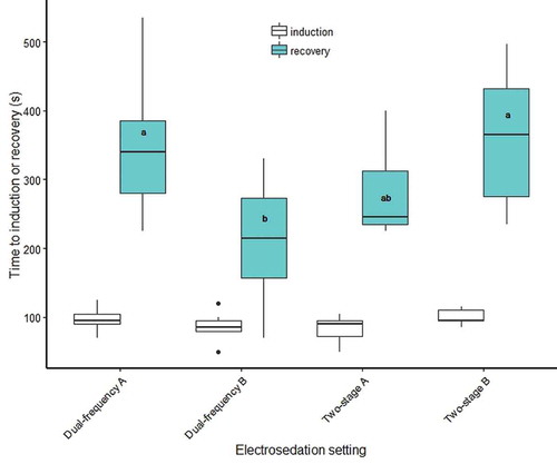
TABLE 2. Numbers of Lake Trout in control and treatment groups that died during the 22-d holding period or had spinal injuries after being exposed to a two-stage electrosedation approach (i.e., 20 s of 60-V continuous DC followed by 20 s of 60-V pulsed DC [30 Hz and 25% duty cycle]) administered via a Portable Electrosedation System unit (Smith-Root, Inc.). Numbers do not include fish that escaped during the 22-d holding period.
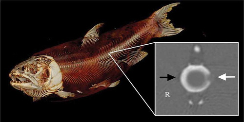
FIGURE 4. Computed tomography (CT) scan of a lean Lake Trout used to evaluate different electrosedation settings for immobilizing fish prior to the implantation of electronic transmitters. The inset (image within the white outlined box) depicts a CT scan of the transverse plane of a vertebral bone exhibiting a minor spinal injury. Within the inset, the white arrow highlights a defect in the left lateral aspect of the vertebral body, and the black arrow points to a normal vertebral body margin on the right (R) side. The ventral aspect of the vertebral body is at the bottom of the image.