3,854
Views
88
CrossRef citations to date
0
Altmetric
Original Articles

Comparison of Different Dilution Methods for Measuring Diesel Particle Emissions

, , , &
Pages 12-23 | Received 01 Sep 2002, Accepted 01 Apr 2003, Published online: 17 Aug 2010

Figures & data

TABLE 1 Engine operating parameters in the experiments

FIG. 1 Schematics describing the different dilution setups applied in the experiments. (a) ED1 + ED2 and SS + ED, (b) PRD + ED and PRD.
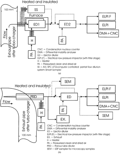
FIG. 1 Schematics describing the different dilution setups applied in the experiments. (a) ED1 + ED2 and SS + ED, (b) PRD + ED and PRD.

FIG. 2 Schematics (not in scale) of the different diluters applied in this study. (a) Ejector diluter (ED), (b) partial flow diluter Smart Sampler (SS), (c) porous tube diluter (PRD).
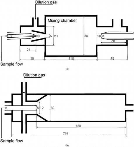
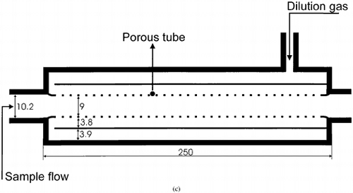
FIG. 2 Schematics (not in scale) of the different diluters applied in this study. (a) Ejector diluter (ED), (b) partial flow diluter Smart Sampler (SS), (c) porous tube diluter (PRD).

TABLE 2 Engine load, dilution ratios, dilution temperatures, total particle number concentrations measured with DMA + CNC, and calculated count median diameters for different dilution systems

FIG. 3 Number size distributions measured with DMA + CNC for different dilution systems and dilution ratios at low load. (a) SS + ED, (b) ED1 + ED2 and PRD + ED, (c) PRD.
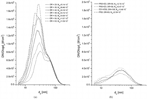
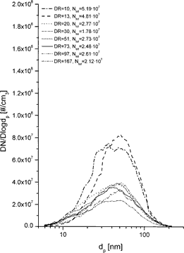
FIG. 3 Number size distributions measured with DMA + CNC for different dilution systems and dilution ratios at low load. (a) SS + ED, (b) ED1 + ED2 and PRD + ED, (c) PRD.

FIG. 4 Number size distributions measured with DMA + CNC for different dilution systems and dilution ratios at high load.
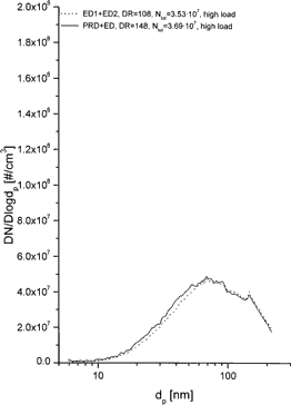
FIG. 4 Number size distributions measured with DMA + CNC for different dilution systems and dilution ratios at high load.

FIG. 5 Count median diameters (CMD) together with geometric standard deviations (σg) and total number concentrations (Ntot) as a function of dilution ratio (DR) for SS + ED (DR(ED) = 11.7, constant) and PRD dilution systems.
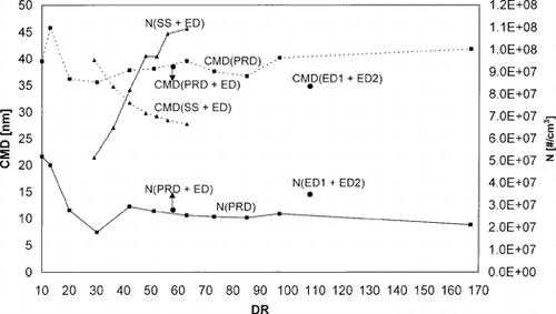
FIG. 5 Count median diameters (CMD) together with geometric standard deviations (σg) and total number concentrations (Ntot) as a function of dilution ratio (DR) for SS + ED (DR(ED) = 11.7, constant) and PRD dilution systems.

FIG. 6 TEM micrographs of individual exhaust gas particles from a turbo-charged off-road diesel engine sampled at the location presented in . (a) An overview of the typical particles found on the sample presenting particles of about 40 nm in size, (b) a close-up of a typical nucleated primary particle of 5–7 nm in size.
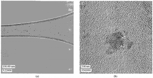
FIG. 6 TEM micrographs of individual exhaust gas particles from a turbo-charged off-road diesel engine sampled at the location presented in Figure 1a. (a) An overview of the typical particles found on the sample presenting particles of about 40 nm in size, (b) a close-up of a typical nucleated primary particle of 5–7 nm in size.

TABLE 3 Estimated residence times in the different diluters

Reprints and Corporate Permissions

Please note: Selecting permissions does not provide access to the full text of the article, please see our help page How do I view content?

To request a reprint or corporate permissions for this article, please click on the relevant link below:

Academic Permissions

Please note: Selecting permissions does not provide access to the full text of the article, please see our help page How do I view content?

Obtain permissions instantly via Rightslink by clicking on the button below:

If you are unable to obtain permissions via Rightslink, please complete and submit this Permissions form. For more information, please visit our Permissions help page.