Figures & data
FIG. 1 Optical pyrometer installation.
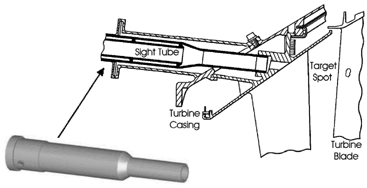
FIG. 2 Fundamental purge design.
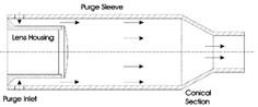
FIG. 3 Air curtain configuration.
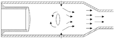
FIG. 4 Air scrubbing configuration.
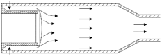
FIG. 5 Still tube configuration.
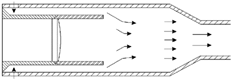
FIG. 6 Mesh for air scrubbing configuration.
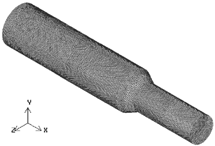
TABLE 1 Boundary conditions for numerical simulations
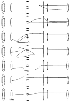
FIG. 7 Purge air pathlines for the air curtain configuration.
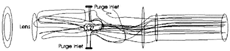
FIG. 8 Purge air pathlines for the air scrubbing configuration.
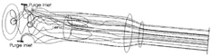
FIG. 9 Purge air pathlines for still tube configuration.
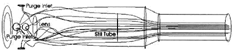
FIG. 10 Recirculations in the air curtain configuration.
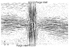
FIG. 11 Backflow in the air curtain configuration.
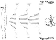
FIG. 12 Recirculation in the air scrubbing configuration.
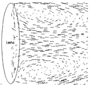
FIG. 13 Purge flow into the still tube.
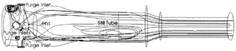
FIG. 14 Recirculatioin in the still tube configuration.
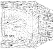
FIG. 15 Flow redirection in front of the still tube mouth.
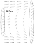
FIG. 16 Level of purge air deposition.
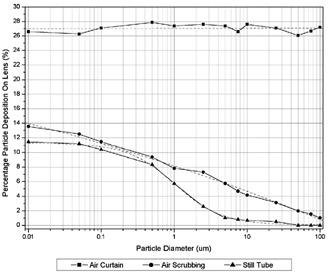
FIG. 17 Purge air deposition in the air curtain configuration.
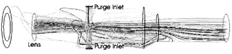
FIG. 18 Purge air deposition in the still tube configuration.
FIG. 19 Turbine chamber penetration in the still tube configuration.
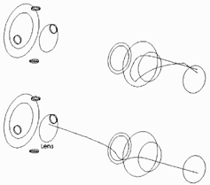
FIG. 20 Level of turbine chamber penetration.
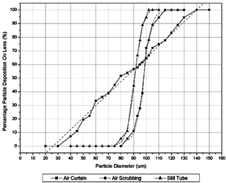
FIG. 21 Turbine chamber penetration in the air curtain configuration.