882
Views
33
CrossRef citations to date
0
Altmetric
Original Articles

Miniature Pipe Bundle Heat Exchanger for Thermophoretic Deposition of Ultrafine Soot Aerosol Particles at High Flow Velocities

, &
Pages 456-466 | Received 01 Sep 2003, Accepted 01 Feb 2004, Published online: 17 Aug 2010

Figures & data

FIG. 1 Cross-sectional area of the miniature pipe bundle heat exchanger. Pipe inner diameter d i = 0.99 mm, outer diameter d o = 1.59 mm. Aerosol flow around the cooling tubes flown through by cooling air.
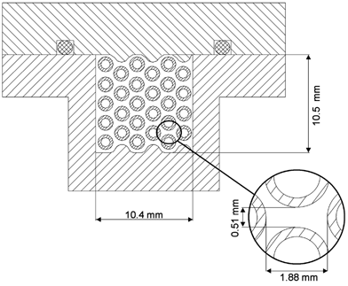
FIG. 1 Cross-sectional area of the miniature pipe bundle heat exchanger. Pipe inner diameter d i = 0.99 mm, outer diameter d o = 1.59 mm. Aerosol flow around the cooling tubes flown through by cooling air.

FIG. 2 Photograph of the pipe bundle heat exchanger inlet section.

FIG. 2 Photograph of the pipe bundle heat exchanger inlet section.

FIG. 3 Longitudinal section of the pipe bundle heat exchanger. Note the symmetrical design of the deposition device.
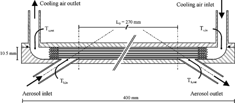
FIG. 3 Longitudinal section of the pipe bundle heat exchanger. Note the symmetrical design of the deposition device.

FIG. 4 Schematic flow diagram of the experimental setup for counterflow heat exchanger particle deposition measurements.
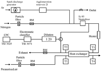
FIG. 4 Schematic flow diagram of the experimental setup for counterflow heat exchanger particle deposition measurements.

TABLE 1 Experimental parameters for the investigation of the particle deposition mechanisms in the miniature pipe bundle heat exchanger

FIG. 5 Soot-particle size distributions measured before and after the heat exchanger in experiment Ia (arithmetic mean ± standard deviation of 6 measurements each).
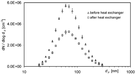
FIG. 5 Soot-particle size distributions measured before and after the heat exchanger in experiment Ia (arithmetic mean ± standard deviation of 6 measurements each).

FIG. 6 Total particle deposition efficiencies ϵtot,i and isothermal losses ϵiso,i in the pipe bundle heat exchanger for experiments Ia–Id. Data points with error bars represent the arithmetic mean ± standard deviation of 11 differential measurement values.
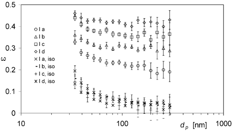
FIG. 6 Total particle deposition efficiencies ϵtot,i and isothermal losses ϵiso,i in the pipe bundle heat exchanger for experiments Ia–Id. Data points with error bars represent the arithmetic mean ± standard deviation of 11 differential measurement values.

FIG. 7 Total particle deposition efficiencies ϵtot,i , isothermal losses ϵiso,i , and thermophoretic deposition efficiencies ϵth,i calculated with f(iso,th) = −ϵth,i · ϵiso,I and f(iso,th) = 0, respectively, for experiment Ia. Data points with error bars represent the arithmetic mean ± standard deviation of 11 differential measurement values; dashed line illustrates ϵth,avg calculated with f(iso,th) = −ϵth,i · ϵiso,i .
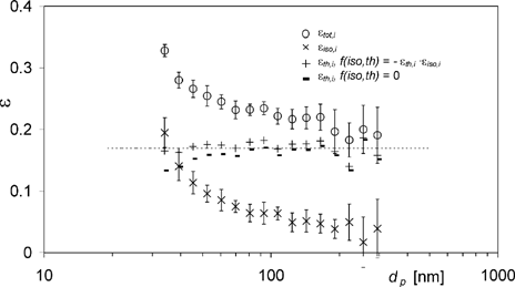
FIG. 7 Total particle deposition efficiencies ϵtot,i , isothermal losses ϵiso,i , and thermophoretic deposition efficiencies ϵth,i calculated with f(iso,th) = −ϵth,i · ϵiso,I and f(iso,th) = 0, respectively, for experiment Ia. Data points with error bars represent the arithmetic mean ± standard deviation of 11 differential measurement values; dashed line illustrates ϵth,avg calculated with f(iso,th) = −ϵth,i · ϵiso,i .

FIG. 8 Total particle deposition efficiency ϵtot,avg plotted against the dimensionless precipitator number calculated from average flow parameters, (Lμ0Δ T log,mean)/(v 0ρ0 T 0 H ch 2). The lines are linear least-squares fits to the data sets with different cooling air flow rates (5 l min− 1 dotted; 10 l min− 1 dashed). Error bars represent the standard deviation (±1 s.d.) of the averaged values ϵtot,i .
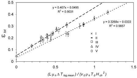
FIG. 8 Total particle deposition efficiency ϵtot,avg plotted against the dimensionless precipitator number calculated from average flow parameters, (Lμ0Δ T log,mean)/(v 0ρ0 T 0 H ch 2). The lines are linear least-squares fits to the data sets with different cooling air flow rates (5 l min− 1 dotted; 10 l min− 1 dashed). Error bars represent the standard deviation (±1 s.d.) of the averaged values ϵtot,i .

FIG. 9 Thermophoretic particle deposition efficiency ϵth,avg plotted against the dimensionless precipitator number calculated from average flow parameters, (Lμ0Δ T log,mean)/(v 0ρ0 T 0 H ch 2). The lines are linear least-squares fits to the data sets with different cooling air flow rates (5 l min− 1 dotted; 10 l min− 1 dashed) and the theoretical relation for a plate precipitator (solid). Error bars represent the standard deviation (±1 s.d.) of the averaged values ϵth,i .
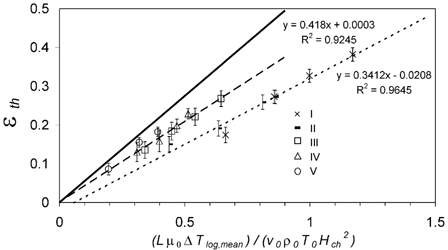
FIG. 9 Thermophoretic particle deposition efficiency ϵth,avg plotted against the dimensionless precipitator number calculated from average flow parameters, (Lμ0Δ T log,mean)/(v 0ρ0 T 0 H ch 2). The lines are linear least-squares fits to the data sets with different cooling air flow rates (5 l min− 1 dotted; 10 l min− 1 dashed) and the theoretical relation for a plate precipitator (solid). Error bars represent the standard deviation (±1 s.d.) of the averaged values ϵth,i .

FIG. 10 Thermophoretic particle deposition efficiency ϵth,i plotted against the dimensionless precipitator number calculated from effective flow parameters at the hot inlet, (L *μ h,inΔ T h,in)/(v h,inρ h,in T h,in H ch 2). The line is the theoretical relation for a plate precipitator. Error bars represent the standard deviation (±1 s.d.) of the averaged values ϵth,i .
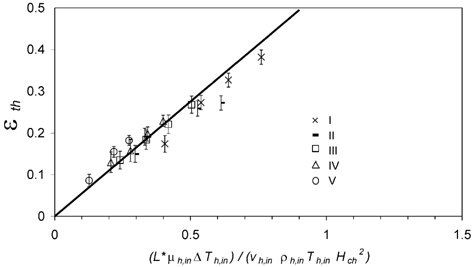
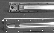
FIG. 10 Thermophoretic particle deposition efficiency ϵth,i plotted against the dimensionless precipitator number calculated from effective flow parameters at the hot inlet, (L *μ h,inΔ T h,in)/(v h,inρ h,in T h,in H ch 2). The line is the theoretical relation for a plate precipitator. Error bars represent the standard deviation (±1 s.d.) of the averaged values ϵth,i .

Reprints and Corporate Permissions

Please note: Selecting permissions does not provide access to the full text of the article, please see our help page How do I view content?

To request a reprint or corporate permissions for this article, please click on the relevant link below:

Academic Permissions

Please note: Selecting permissions does not provide access to the full text of the article, please see our help page How do I view content?

Obtain permissions instantly via Rightslink by clicking on the button below:

If you are unable to obtain permissions via Rightslink, please complete and submit this Permissions form. For more information, please visit our Permissions help page.