Figures & data
Figure 1 Structure and regions of the human nasal airway replica (a) schematic diagram, (b) physical model.
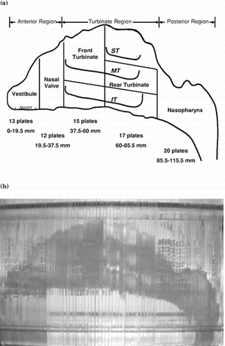
Figure 2 Characteristics of carbon fibers: (a) microscopic view, (b) diameter, and (c) length distribution.
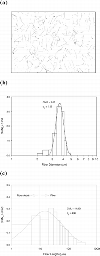
Figure 3 Schematic diagram of the experimental setup for the fiber deposition study.
Figure 4 Fiber counting/measuring with G22 Walton-Beckett gratitude (under 400× magnification).
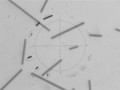
Figure 5 Fiber deposition map for an inspiratory flow rate of 7.5 l/min. Deposition fractions for each region and subregion are shown in percent (0 represents the value of the fraction < 0.5%).
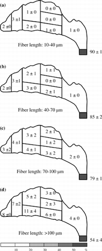
Figure 6 Fiber deposition map for an inspiratory flow rate of 15 l/min. Deposition fractions for each region and subregion are shown in percent (0 represents the value of the fraction < 0.5%).
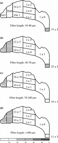
Figure 7 Fiber deposition map for an inspiratory flow rate of 30 l/min. Deposition fractions for each region and subregion are shown in percent (0 represents the value of the fraction < 0.5%).
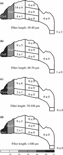
Figure 8 Fiber deposition map for an inspiratory flow rate of 43.5 l/min. Deposition fractions for each region and subregion are shown in percent (0 represents the value of the fraction < 0.5%).
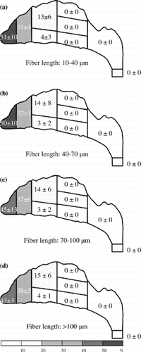
Figure 9 The deposition efficiency as a function of impaction parameter for fiber deposition in the human nasal airway.
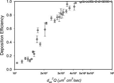
Figure 10 Deposition efficiency as function of fiber length for fiber deposition in the human nasal airway using different inspiratory flow rates.
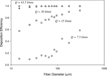
Figure 11 Fiber deposition in the vestibule area for a inspiratory flow rate of (a) Q = 7.5 l/min, and (b) Q = 30.0 l/min (bottom view of the nostril entrance).
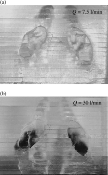
Figure 12 Comparison of fiber deposition fraction in the anterior region and filter for (a) short fibers with fiber length 10–20 μ m, and (b) long fibers with fiber length > 200 μ m.
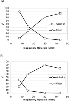
Figure 13 Fiber deposition fraction in the turbinate region (a) short fibers with fiber length 10–20 μ m, and (b) long fibers with fiber length > 200 μ m. (ST, MT, and IT: superior, middle, and inferior turbinate, respectively.)
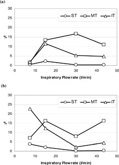
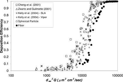
Figure 14 Comparison of deposition efficiencies between fibers and spherical particles.