Figures & data
Figure 1 Relative standard deviation over time for each size channel, according to the SMPS measurements. Only size channels in which counting statistics contributed to less than 20% of the given variability were included.
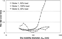
Figure 2 The result from IC analysis of LPI samples and filter samples (stacked filter unit, CitationPagels et al. 2003). Each bar represents an average value taken of n filters. The geometrical mean diameter of particles given in each impactor stage is given in (nm).
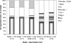
Figure 3 Size-resolved sulfur to chlorine mass ratio from PIXE analysis of the LPI substrates.
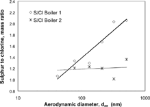
Figure 4 Diameter growth factor for the RH scans performed in boiler 1 together with calculated diameter growth factor according to the ZSR mixing rule. In the model, chemical composition based on IC analysis of filter samples was used. The growth of the pure compounds is also shown.
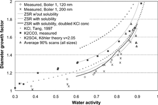
Table 1 Hygroscopic properties of particles sampled in boiler 1 and 2
Figure 5 The hygroscopic diameter growth factor, individual scans, and average values. The time series for boiler 1 is divided into high and low load. Error bars correspond to the estimated instrumental error. The larger error bars in boiler 1 are due to a larger uncertainty in RH during this measurement.
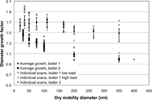
Figure 6 Example of typical humidified size distributions measured in DMA2. The size distributions were often relatively narrow but occasionally a bimodal hygroscopic growth appeared indicating a clearly external mixture. The selected dry sizes were 110 nm for boiler 1 and 100 nm for boiler 2, indicated with a bar in the figure.
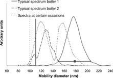
Figure 7 RH scans for boiler 2, original data (Gf B ) as well as data corrected with respect to fractal structure (Gf ve ). The calculations made by the ZSR mixing rule are based on chemical composition from IC analysis of filter samples.
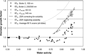
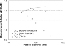
Figure 8 Size scans, boiler 2, showing both Gf B and Gf ve , calculated taking the fractal-like shape into account (Df =2.49, C 3 = 0.563). The solid line shows the theoretical Gf ve of a compound having a constant chemical composition over size.