1,495
Views
19
CrossRef citations to date
0
Altmetric
Original Articles

Characterization of Fine Particulate Emissions from Casting Processes

, , , , &
Pages 947-959 | Received 12 May 2005, Accepted 25 Aug 2005, Published online: 23 Feb 2007

Figures & data

Figure 1 Schematic of the casting process and sampling location in the Research Foundry at Technikon, LLC (McClellan, CA).
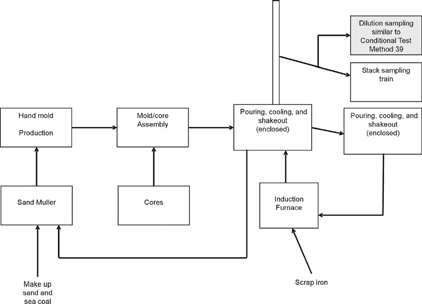
Figure 1 Schematic of the casting process and sampling location in the Research Foundry at Technikon, LLC (McClellan, CA).

Figure 2 Schematic of the Desert Research Institute (DRI, Reno, NV) Source Dilution Sampling System.
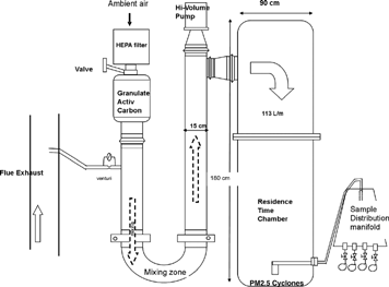
Figure 2 Schematic of the Desert Research Institute (DRI, Reno, NV) Source Dilution Sampling System.

TABLE 1 Daily test conditions for comparisons of the dilution sampling method and U.S. Environmental Protection Agency (EPA) Modified Method 201A (Conditional Test Method 040)/202 sampling train from the Research Foundry at Technikon, LLC (McClellan, CA) from February 25–27, 2004

TABLE 2 PM2.5 mass concentrations determined by filter sampler and electronic low-pressure impactor (ELPI) with DRI source dilution sampling system (similar to U.S. Environmental Protection Agency [EPA] Conditional Test Method 039)

TABLE 3 Emission factors of PM2.5 chemical species from the foundry process (4-on irregular gear No-Bake® molds). No weighing factors for metal oxides and organic carbon are applied

Figure 3 Process variations of stack temperature (°C), carbon monoxide (CO) concentration (ppm), and total hydrocarbon concentration (THC) (ppm), measured in: (a) Run 3, (b) Run 4, (c) Run 5, and (d) Run 6. (Note that peak stack temperature [°C] in Runs 5 and 6 during shakeout period exceeds 300°C; in Runs 3 and 4 it is ∼ 200°C.)

Figure 3 Process variations of stack temperature (°C), carbon monoxide (CO) concentration (ppm), and total hydrocarbon concentration (THC) (ppm), measured in: (a) Run 3, (b) Run 4, (c) Run 5, and (d) Run 6. (Note that peak stack temperature [°C] in Runs 5 and 6 during shakeout period exceeds 300°C; in Runs 3 and 4 it is ∼ 200°C.)

Figure 4 Process variations of PM2.5 concentration (4 μg/m3) and number concentrations (particles/cc) measured by ELPI for: (a) Run 3, (b) Run 4, (c) Run 5, and (d) Run 6. (Note that PM2.5 mass concentrations in Runs 5 and 6 are approximately twice those of Runs 3 and 4, whereas PM2.5 number concentrations are similar.)
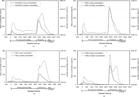
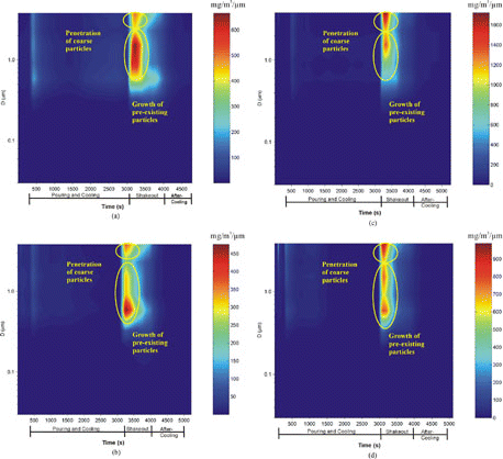
Figure 4 Process variations of PM2.5 concentration (4 μg/m3) and number concentrations (particles/cc) measured by ELPI for: (a) Run 3, (b) Run 4, (c) Run 5, and (d) Run 6. (Note that PM2.5 mass concentrations in Runs 5 and 6 are approximately twice those of Runs 3 and 4, whereas PM2.5 number concentrations are similar.)
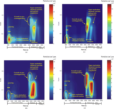
TABLE 4 Average PM2.5 mass fraction determined by Electrical Low-Pressure Impactor (ELPI)

Figure 5 Distribution of calculated in-stack particle mass concentrations (mg/cm3/μm) for: (a) Run 3, (b) Run 4, (c) Run 5, and (d) Run 6.

Figure 5 Distribution of calculated in-stack particle mass concentrations (mg/cm3/μm) for: (a) Run 3, (b) Run 4, (c) Run 5, and (d) Run 6.

Figure 6 Distribution of calculated in-stack particle number concentrations (particles/cc/m) for: (a) Run 3, (b) Run 4, (c) Run 5, and (d) Run 6.

Figure 6 Distribution of calculated in-stack particle number concentrations (particles/cc/m) for: (a) Run 3, (b) Run 4, (c) Run 5, and (d) Run 6.

Reprints and Corporate Permissions

Please note: Selecting permissions does not provide access to the full text of the article, please see our help page How do I view content?

To request a reprint or corporate permissions for this article, please click on the relevant link below:

Academic Permissions

Please note: Selecting permissions does not provide access to the full text of the article, please see our help page How do I view content?

Obtain permissions instantly via Rightslink by clicking on the button below:

If you are unable to obtain permissions via Rightslink, please complete and submit this Permissions form. For more information, please visit our Permissions help page.