Figures & data
FIG. 1 Schematic diagram of the experimental setup used to evaluate the flow mixing in the NanoDMA when operated with different gases for the sheath and aerosol carrier flow.
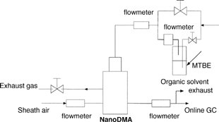
FIG. 2 Schematic diagram of the experimental setup used to investigate the sizing accuracy of Nano-DMA operated with different gases for the sheath and aerosol carrier flow.
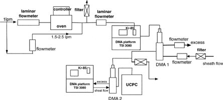
TABLE 1 Ratios of MTBE (methyl tert-butyl ether) vapor concentration in the monodisperse-aerosol-carrier flow to that in the polydisperse-aerosol-carrier flow when the Nano-DMA operates with different gases for sheath and aerosol-carrier flows (pairing among He, Ar, N2, and CO2): 7.5 lpm for the sheath flowrate and 1.5 lpm for the aerosol-carrier flowrate
TABLE 2 Binary diffusivities of different inert gas mixtures (pairing among He, Ar, N2, and CO2) and diffusion lengths at flow rates of 7.5 and 15 lpm
TABLE 3 Ratios of MTBE (methyl tert-butyl ether) vapor concentration in the monodisperse-aerosol-carrier flow to that in the polydisperse-aerosol-carrier flow when the Nano-DMA operates with different gases for sheath and aerosol-carrier flows (pairing among He, Ar, N2, and CO2): 15 lpm for the sheath flowrate and 1.5 lpm for the aerosol-carrier flowrate
TABLE 4 Gas properties (viscosity and mean free path) of Ar, N2, and He at 20°C used in Equation (Equation4)
FIG. 3 Comparison of estimated, Dp1, and measured, Dp2, particle sizes for the gas pairs of (a) Ar-Ar and (b) N2-N2. The sheath and aerosol-carrier flowrates were kept 15 and 1.5 lpm, respectively. The estimated particle size was based on the gas property of the sheath flow used in the Nano-DMA.
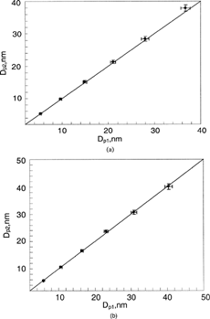
FIG. 4 Comparison of estimated, Dp1, and measured, Dp2, particle sizes when Nano-DMA was operated with the Ar-N2 composition: (a) Ar as the aerosol-carrier gas and N2 as the sheath gas; (b) N2 as the aerosol carrier gas and Ar as the sheath gas. The sheath and aerosol-carrier flowrates were kept at 15 and 1.5 lpm, respectively. The estimated particle size was based on the gas property of the sheath flow used in the Nano-DMA.
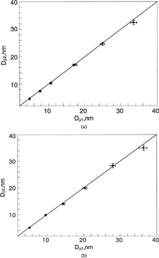
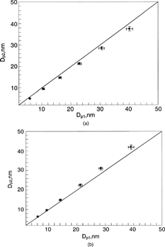
FIG. 5 Comparisons of estimated, Dp1, and measured, Dp2, particle sizes when Nano-DMA was operated with the gas combination of He-Ar: (a) Ar as the sheath flow and He as the aerosol carrier flow; (b) He as the sheath flow and Ar as the aerosol carrier flow. The sheath and aerosol-carrier flowrates were kept at 15 and 1.5 lpm, respectively. The estimated particle size was based on the gas property of the sheath flow used in the Nano-DMA.
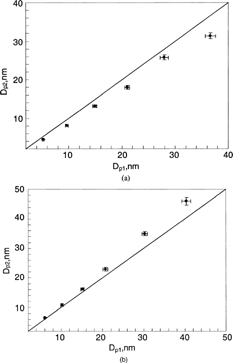
FIG. 6 Comparisons of estimated, Dp1, and measured, Dp2, particle sizes when Nano-DMA was operated with the combination of He-N2: (a) N2 as the sheath flow and He as the aerosol carrier flow; (b) He as the sheath flow and N2 as the aerosol carrier flow. The sheath and aerosol-carrier flowrates were kept at 15 and 1.5 lpm, respectively. The estimated particle size was based on the gas property of the sheath flow used in the Nano-DMA.
