922
Views
1
CrossRef citations to date
0
Altmetric
Original Articles

Automated Low-Pressure Carbonate Eluent Ion Chromatography System with Postsuppressor Carbon Dioxide Removal for the Analysis of Atmospheric Gases and Particles

, &
Pages 1072-1084 | Received 11 Aug 2005, Accepted 19 Oct 2005, Published online: 23 Feb 2007

Figures & data

FIG. 1 Sensor circuit for controlling the P1 peristaltic pump for PC sample. C: capacitor; M: metal oxide semi conductor field effect transistor switch, PC: particle collector; Relay: SPDT relay; S: sensor to electrode connection.
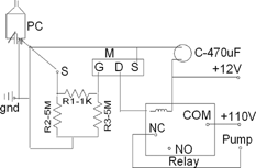
FIG. 1 Sensor circuit for controlling the P1 peristaltic pump for PC sample. C: capacitor; M: metal oxide semi conductor field effect transistor switch, PC: particle collector; Relay: SPDT relay; S: sensor to electrode connection.

FIG. 2 Instrument schematic for gas particle ion chromatography system. hydrogen peroxide: 0.5 mM hydrogen peroxide solution; PP: peristaltic pump (12 channel); AI: air inlet; WT: water trap; F: filter; MFC: mass flow controller; AP: air pump; AO: air outlet; PPWD1 and PPWD2: parallel plate wet diffusion denuder1 and 2; PC: particle collector; Cy: cyclone; SST: stainless steel tube; GS: gas sample; PS: particle sample; L1: injection loop1; L2: injection loop2; V1: 3 way valve; V2: 6 port valve; V3: 10 port valve (high pressure); V4: 10 port valve (high pressure); V5: 10 port valve (low pressure); ATD: ammonia transfer device; MB: mixed bed resin; W: waste; D1: conductivity detector1; D2: conductivity detector2; R, restrictor tube; CC: cation concentrator; AC: anion concentrator (TAC-ULP1); GC: anion guard column; SC: anion separation column (short separation column); SUPP: suppressor; CRD: carbon dioxide removal device; Std. Soln.: standard solution.
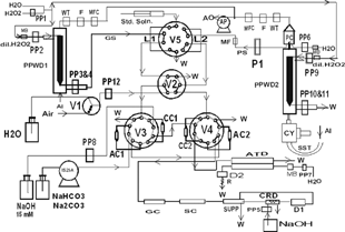
FIG. 2 Instrument schematic for gas particle ion chromatography system. hydrogen peroxide: 0.5 mM hydrogen peroxide solution; PP: peristaltic pump (12 channel); AI: air inlet; WT: water trap; F: filter; MFC: mass flow controller; AP: air pump; AO: air outlet; PPWD1 and PPWD2: parallel plate wet diffusion denuder1 and 2; PC: particle collector; Cy: cyclone; SST: stainless steel tube; GS: gas sample; PS: particle sample; L1: injection loop1; L2: injection loop2; V1: 3 way valve; V2: 6 port valve; V3: 10 port valve (high pressure); V4: 10 port valve (high pressure); V5: 10 port valve (low pressure); ATD: ammonia transfer device; MB: mixed bed resin; W: waste; D1: conductivity detector1; D2: conductivity detector2; R, restrictor tube; CC: cation concentrator; AC: anion concentrator (TAC-ULP1); GC: anion guard column; SC: anion separation column (short separation column); SUPP: suppressor; CRD: carbon dioxide removal device; Std. Soln.: standard solution.

FIG. 3 Field installation of gas collection system (GCS) and particle collection system (PCS). PVC: 4″ PVC pipe; PC: particle collector; H2O2 In: 0.5 mM hydrogen peroxide inlet; Cy: Cyclone for 2.5 micron cutpoint; SST: stainless steel tube; BF: blower fan; WT: water trap; F: minicapsule filter; MFC: mass flow controller; AP: air pump.
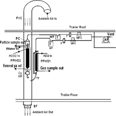
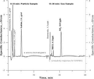
FIG. 3 Field installation of gas collection system (GCS) and particle collection system (PCS). PVC: 4″ PVC pipe; PC: particle collector; H2O2 In: 0.5 mM hydrogen peroxide inlet; Cy: Cyclone for 2.5 micron cutpoint; SST: stainless steel tube; BF: blower fan; WT: water trap; F: minicapsule filter; MFC: mass flow controller; AP: air pump.
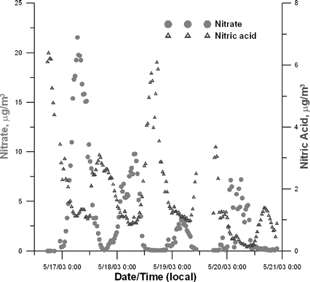
TABLE 1 Timetable for different valves and their operational actions. (B = Black, G = Grey)

FIG. 4 Typical instrument output for 30 min cycle including both anion chromatogram conductivity response traces for ammonium/ammonia.

FIG. 4 Typical instrument output for 30 min cycle including both anion chromatogram conductivity response traces for ammonium/ammonia.

FIG. 5 Nitrate and nitric acid concentration for May 16–21, 2003 in Bondville, IL.

FIG. 5 Nitrate and nitric acid concentration for May 16–21, 2003 in Bondville, IL.

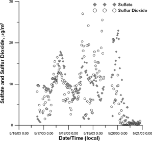
FIG. 6 Sulfate and sulfur dioxide concentration for May 16–21, 2003 in Bondville, IL.

FIG. 6 Sulfate and sulfur dioxide concentration for May 16–21, 2003 in Bondville, IL.

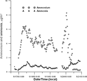
FIG. 7 Ammonium and ammonia concentration for May 16–21, 2003 in Bondville, IL.

FIG. 7 Ammonium and ammonia concentration for May 16–21, 2003 in Bondville, IL.

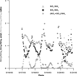
FIG. 8 Nitrate/ammonium, Sulfate/ammonium and (nitrate + sulfate)/ ammonium ratios (in equivalents) for May 16–21, 2003 in Bondville, IL.

FIG. 8 Nitrate/ammonium, Sulfate/ammonium and (nitrate + sulfate)/ ammonium ratios (in equivalents) for May 16–21, 2003 in Bondville, IL.

Reprints and Corporate Permissions

Please note: Selecting permissions does not provide access to the full text of the article, please see our help page How do I view content?

To request a reprint or corporate permissions for this article, please click on the relevant link below:

Academic Permissions

Please note: Selecting permissions does not provide access to the full text of the article, please see our help page How do I view content?

Obtain permissions instantly via Rightslink by clicking on the button below:

If you are unable to obtain permissions via Rightslink, please complete and submit this Permissions form. For more information, please visit our Permissions help page.