2,443
Views
69
CrossRef citations to date
0
Altmetric
Original Articles

Measuring Particulate Mass Emissions with the Electrical Low Pressure Impactor

, &
Pages 68-79 | Received 04 May 2005, Accepted 10 Nov 2005, Published online: 23 Feb 2007

Figures & data

TABLE 1 Effective charging efficiency

FIG. 1 Mass-weighted particle size distributions as calculated by the standard ELPI data reduction. The data, plotted as smoothed curves instead of histograms, are from a current model light duty diesel vehicle run over the New European Driving Cycle (NEDC) drive cycle. The numbers label specific points of discussion in the text.
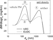
FIG. 1 Mass-weighted particle size distributions as calculated by the standard ELPI data reduction. The data, plotted as smoothed curves instead of histograms, are from a current model light duty diesel vehicle run over the New European Driving Cycle (NEDC) drive cycle. The numbers label specific points of discussion in the text.

FIG. 2 Comparison of mass weighted size distributions recorded with greased aluminum foil versus sintered metal substrates at levels of 8.8× and 71× secondary dilution. The PM data, plotted as smoothed curves, are from the exhaust of a GDI vehicle sampled at constant volume into a dilution tunnel operating at a flow rate of 17 m3/min.
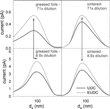
FIG. 2 Comparison of mass weighted size distributions recorded with greased aluminum foil versus sintered metal substrates at levels of 8.8× and 71× secondary dilution. The PM data, plotted as smoothed curves, are from the exhaust of a GDI vehicle sampled at constant volume into a dilution tunnel operating at a flow rate of 17 m3/min.

FIG. 3 ELPI analysis of mobility-selected poly alpha olefin oil particles comparing the response of greased foil and sintered collection plates. The data are corrected for multiply charged particles transmitted by the differential mobility analyzer. Lines represent raw ELPI currents; points illustrate fits to the impactor efficiency curves.
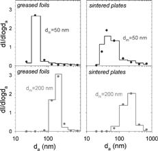
FIG. 3 ELPI analysis of mobility-selected poly alpha olefin oil particles comparing the response of greased foil and sintered collection plates. The data are corrected for multiply charged particles transmitted by the differential mobility analyzer. Lines represent raw ELPI currents; points illustrate fits to the impactor efficiency curves.

FIG. 4 Comparison of a normalized soot size distribution, with σ g = 1.7, plotted against mobility diameter (d = d m ) versus aerodynamic diameter (d = d a ). Vertical tick marks indicate D50 cut points of the ELPI sintered stages.
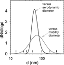
FIG. 4 Comparison of a normalized soot size distribution, with σ g = 1.7, plotted against mobility diameter (d = d m ) versus aerodynamic diameter (d = d a ). Vertical tick marks indicate D50 cut points of the ELPI sintered stages.

FIG. 5 Calibration of the ELPI cascade impactor for greased Al foils and sintered collection plates using mobility size selected oil droplets. Measured d m are calculated from the ELPI currents by fitting them to the impactor efficiency curves, Equations. (4)–(6), to obtain d a , and converting the latter to mobility diameter via Equation (Equation2). Based on these results small refinements were made to the factory calibrated D50 cut points of the sintered stages.
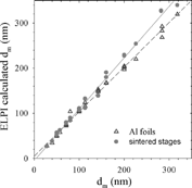
FIG. 5 Calibration of the ELPI cascade impactor for greased Al foils and sintered collection plates using mobility size selected oil droplets. Measured d m are calculated from the ELPI currents by fitting them to the impactor efficiency curves, Equations. (4)–(6), to obtain d a , and converting the latter to mobility diameter via Equation (Equation2). Based on these results small refinements were made to the factory calibrated D50 cut points of the sintered stages.

TABLE 2 Impactor characteristics for sintered collection plates

FIG. 6 Time integrated current distributions of PM sampled from light duty diesel vehicle exhaust. Histograms depict the raw currents in units of femtoamp seconds. Points represent the best fits to a lognormal mobility size distribution. The best fit mean mobility diameters for bags 1, 2, and 3 are μ g = 67, 61, and 71 nm, respectively, with 95% confidence intervals of ± 12%.
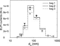
FIG. 6 Time integrated current distributions of PM sampled from light duty diesel vehicle exhaust. Histograms depict the raw currents in units of femtoamp seconds. Points represent the best fits to a lognormal mobility size distribution. The best fit mean mobility diameters for bags 1, 2, and 3 are μ g = 67, 61, and 71 nm, respectively, with 95% confidence intervals of ± 12%.

FIG. 7 Comparison of PM mass emissions from a light duty diesel vehicle obtained by the standard ELPI data reduction, the fitting procedure described in this paper, and filter collection using Teflo and TX40 filter media.
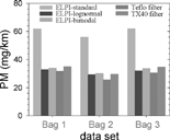
FIG. 7 Comparison of PM mass emissions from a light duty diesel vehicle obtained by the standard ELPI data reduction, the fitting procedure described in this paper, and filter collection using Teflo and TX40 filter media.

FIG. 8 ELPI versus filter data for light duty diesel vehicle exhaust PM mass emissions. Unmarked filter data are gravimetric measurements using Teflo filters. Data marked with an * show the total carbon measured with quartz filters and analyzed by the Horiba 1370PM.
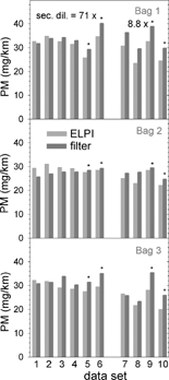
FIG. 8 ELPI versus filter data for light duty diesel vehicle exhaust PM mass emissions. Unmarked filter data are gravimetric measurements using Teflo filters. Data marked with an * show the total carbon measured with quartz filters and analyzed by the Horiba 1370PM.

FIG. 9 ELPI versus gravimetric measurements of GDI vehicle exhaust PM mass emissions. Data are shown for the urban and extra-urban portions of the NEDC (first pair and second pair bars in tests 1–4) and for phases 1–3 of the FTP cycle (first, second, and third pair of bars 5–6).
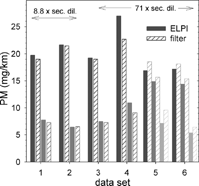
FIG. 9 ELPI versus gravimetric measurements of GDI vehicle exhaust PM mass emissions. Data are shown for the urban and extra-urban portions of the NEDC (first pair and second pair bars in tests 1–4) and for phases 1–3 of the FTP cycle (first, second, and third pair of bars 5–6).

FIG. 10 ELPI versus filter based measurements of DPF equipped diesel and PFI gasoline vehicle exhaust PM mass emissions. The three pairs of data for each vehicle/test correspond to bags 1, 2, and 3 of the FTP cycle. Teflo filters and gravimetric analysis was used for the gasoline vehicles, whereas quartz filters and carbon analysis by the Horiba 1370PM was used for the DPF equipped diesel vehicle. (a) DPF equipped diesel and gasoline vehicle 1. (b) Gasoline vehicle 2.
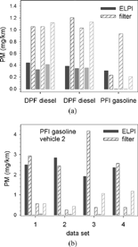
FIG. 10 ELPI versus filter based measurements of DPF equipped diesel and PFI gasoline vehicle exhaust PM mass emissions. The three pairs of data for each vehicle/test correspond to bags 1, 2, and 3 of the FTP cycle. Teflo filters and gravimetric analysis was used for the gasoline vehicles, whereas quartz filters and carbon analysis by the Horiba 1370PM was used for the DPF equipped diesel vehicle. (a) DPF equipped diesel and gasoline vehicle 1. (b) Gasoline vehicle 2.

FIG. 11 The effect of particle density on the determination of number concentration, mobility diameter, and PM mass from ELPI currents.
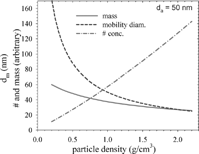
FIG. 11 The effect of particle density on the determination of number concentration, mobility diameter, and PM mass from ELPI currents.

FIG. 12 Soot particle effective density versus mobility diameter.

FIG. 12 Soot particle effective density versus mobility diameter.

FIG. 13 Fitting of ELPI currents when the underlying size distribution is bimodal. (a) Raw ELPI currents and the best fit to two lognormal distributions. (b) Mobility distribution measured by SMPS and derived from the ELPI data.
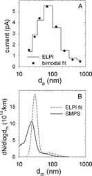
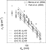
FIG. 13 Fitting of ELPI currents when the underlying size distribution is bimodal. (a) Raw ELPI currents and the best fit to two lognormal distributions. (b) Mobility distribution measured by SMPS and derived from the ELPI data.

Reprints and Corporate Permissions

Please note: Selecting permissions does not provide access to the full text of the article, please see our help page How do I view content?

To request a reprint or corporate permissions for this article, please click on the relevant link below:

Academic Permissions

Please note: Selecting permissions does not provide access to the full text of the article, please see our help page How do I view content?

Obtain permissions instantly via Rightslink by clicking on the button below:

If you are unable to obtain permissions via Rightslink, please complete and submit this Permissions form. For more information, please visit our Permissions help page.