Figures & data
FIG. 1 Schematic diagram of particle generation system NPG-100 and nose-exposure chamber SIS-20MB. Q1–Q4 refer to flow rates, and T1–T3 refer to measured internal temperatures of mantle heater, furnace, and cooler, respectively. SUS: pipe made of stainless steel.
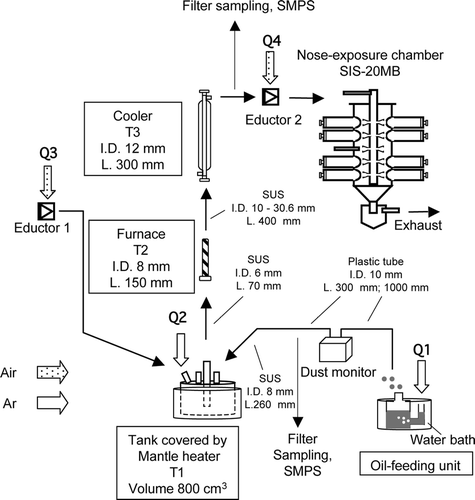
TABLE 1 Measured properties of oil used in this study. N.M. = not measured
FIG. 2 Number size distribution of oil particles generated under the standard operating conditions listed in (measured with SMPS 3936 and 3034).
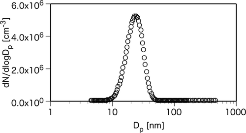
TABLE 2 Operating variables of NPG-100 and the standard operating conditions to generate 20 nm oil particles. Q1–Q4 and T1–T3 correspond to argon and air flow rates and measured internal temperatures shown in , respectively
FIG. 3 Time series of modal diameter, number geometric mean diameter, and total number concentrations (measured with SMPS 3936; 4–160 nm). Oil particles were generated under the standard operating conditions listed in .
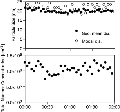
FIG. 4 Reproducibility test results of modal diameter, number geometric mean diameter, and total number concentrations (measured with SMPS 3936; 4–160 nm). Oil particles were generated under the standard operating conditions listed in . Plotted points indicate mean values of each 2-h period, and vertical bars indicate standard deviation.
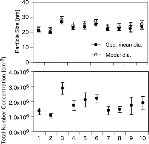
FIG. 5 Number size distributions of particles in the system background (BG; ambient temperature with no oil supply), oil supply with ambient temperature (Oil*), and oil particles generated under the standard operating condition (Oil) measured with SMPS model 3034 and OPC. No particles larger than 300 nm were detected with the OPC in BG.
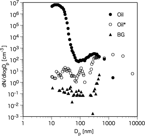
TABLE 3 Parameters of size distributions of oil particles generated under the different oil feed rate (measured with SMPS 3936; 4–160 nm). The other parameters were fixed at standard operating conditions listed in
TABLE 4 Parameters of size distributions of oil particles generated under different temperatures of mantle heater and furnace (measured with SMPS 3936; 4–160 nm). Corresponding number size distributions are shown in and
FIG. 6 Number size distributions of oil particles generated under different mantle heater temperatures (T1). The other parameters were fixed at standard operating parameters listed in .
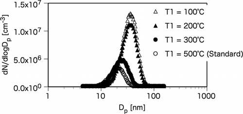
FIG. 7 Number size distributions of oil particles generated under various furnace (T2) and mantle heater (T1) temperatures. The other parameters were fixed at standard operating conditions listed in .
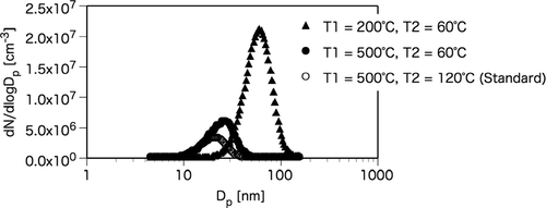
FIG. 8 Number size distributions of oil particles of different oils generated under the standard operating conditions listed in . Each oil feed rate was set to 3.20 μg min−1 by changing the temperature of the water bath.
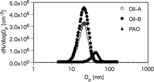
TABLE 5 Parameters of size distributions of oil particles of different oils generated under the standard operating conditions (measured with SMPS 3936; 4–160 nm). Each oil feed rate was set to 3.20 μg min−1 by changing the temperature of the water bath. Corresponding number size distributions are shown in
FIG. 9 Volume-weighted size distributions of particles in the system background (BG), oil supply with ambient temperature (Oil*), and oil particles generated under the standard operating conditions (Oil) measured with SMPS model 3936, 3034, and the OPC. No particles larger than 300 nm were detected with the OPC in BG.
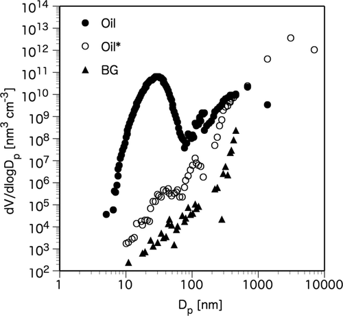
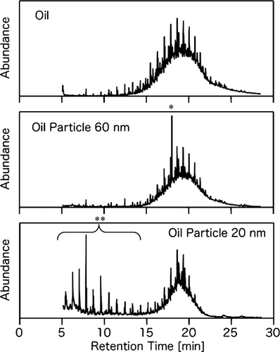
FIG. 10 Ion chromatograms (m/z 57) measured with TD-GC/MS. The chromatograms are oil particles with different size (a modal diameter 20 nm; generated under the standard operating conditions, 60 nm; generated under the standard operating conditions except for T1 = 200°C and T2 = 60°C) and original oil. * and ** indicate contaminations of diethylhexyl phthalate and some contamination or pyrolysis product of oil compounds, respectively.
