5,881
Views
125
CrossRef citations to date
0
Altmetric
Original Articles

Particulate Emissions from a Low-Speed Marine Diesel Engine

, , , &
Pages 24-32 | Received 23 Feb 2005, Accepted 09 Oct 2006, Published online: 02 Feb 2007

Figures & data

FIG. 1 Photograph of the RTX-3 test engine.

FIG. 1 Photograph of the RTX-3 test engine.

TABLE 1 Engine specifications

TABLE 2 Operation points and associated corresponding exhaust gas temperatures, which were recorded during measurement

TABLE 3 Major fuel specifications

FIG. 2 Experimental setup: right unit for taking filter samples, left unit for measuring the particle size distribution. The left-most path is necessary to assure the correct flow rate for isokinetic sampling (MFC: mass flow controller).
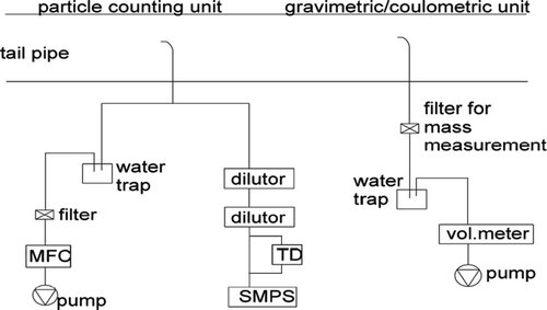
FIG. 2 Experimental setup: right unit for taking filter samples, left unit for measuring the particle size distribution. The left-most path is necessary to assure the correct flow rate for isokinetic sampling (MFC: mass flow controller).

TABLE 4 Temperature settings of the experiment

FIG. 3 Average SMPS size distributions as measured at 1% load with (thin line and thin line with cross) and without TD (thick line and dotted line). The measurement was performed twice.
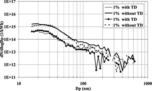
FIG. 3 Average SMPS size distributions as measured at 1% load with (thin line and thin line with cross) and without TD (thick line and dotted line). The measurement was performed twice.

FIG. 4 Average SMPS size distributions as measured at 100% load with (thin line) and without TD (thick line).
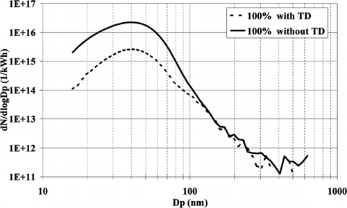
FIG. 4 Average SMPS size distributions as measured at 100% load with (thin line) and without TD (thick line).

FIG. 5 Average SMPS size distributions as measured at 75% load with (thin line) and without TD (thick line).
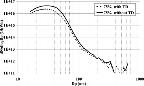
FIG. 5 Average SMPS size distributions as measured at 75% load with (thin line) and without TD (thick line).

FIG. 6 Average SMPS size distributions as measured at 50% load with (thin line) and without TD (thick line).
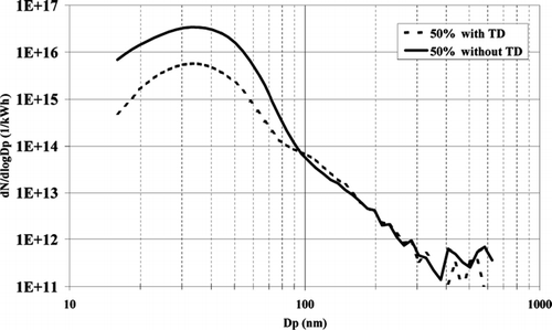
FIG. 6 Average SMPS size distributions as measured at 50% load with (thin line) and without TD (thick line).

FIG. 7 Average SMPS size distributions as measured at 25% load with (thin line) and without TD (thick line).
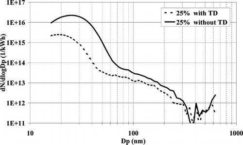
FIG. 7 Average SMPS size distributions as measured at 25% load with (thin line) and without TD (thick line).

FIG. 8 Total number concentrations as calculated from the size distributions for each load point.

FIG. 8 Total number concentrations as calculated from the size distributions for each load point.

FIG. 9 Particle diameter as function of engine load. Measurements were performed with and without TD.
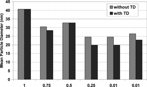
FIG. 9 Particle diameter as function of engine load. Measurements were performed with and without TD.

FIG. 10 Typical number size distributions for this marine diesel engine (circles) at 100% load and a diesel passenger car (triangles) at 100% load.
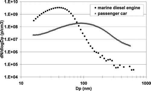
FIG. 10 Typical number size distributions for this marine diesel engine (circles) at 100% load and a diesel passenger car (triangles) at 100% load.

TABLE 5 Comparison of gravimetric particle mass from filter samples and masses as calculated from number size distributions measured with and without TD. Mass unit is corrected for ambient conditions and given in mg/Nm3 (milligram/norm cubic centimeter) unless otherwise indicated

FIG. 11 Summary of results from coulometric analysis and extraction of organic material (OC, organic fraction; EC, elemental carbon; SOF, soluble organic fraction; WSF, water soluble fraction).
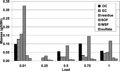
FIG. 11 Summary of results from coulometric analysis and extraction of organic material (OC, organic fraction; EC, elemental carbon; SOF, soluble organic fraction; WSF, water soluble fraction).

FIG. 12 (a) Total number concentrations as calculated from number size distributions and (b) mean particle diameter as measured at 1% load with both fuels.
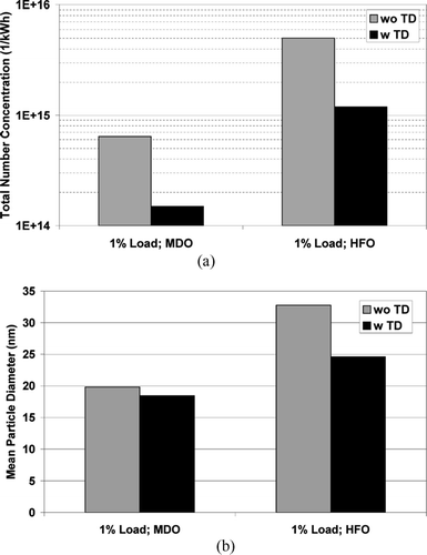
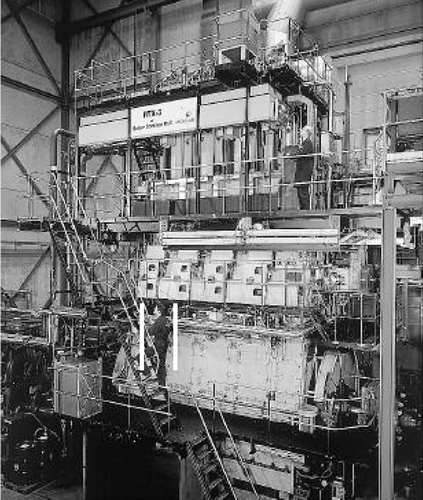
FIG. 12 (a) Total number concentrations as calculated from number size distributions and (b) mean particle diameter as measured at 1% load with both fuels.
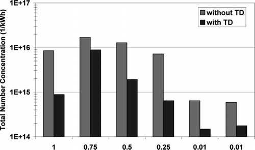
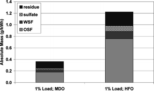
FIG. 13 Absolute masses as extracted from filters sampled at 1% load with both fuels.

FIG. 13 Absolute masses as extracted from filters sampled at 1% load with both fuels.

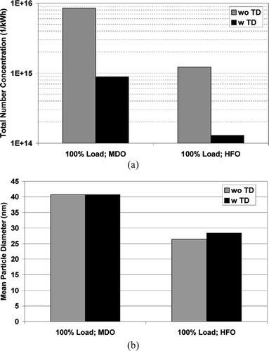
FIG. 14 (a) Total number concentrations as calculated from number size distributions and (b) mean particle diameter as measured at 100% load with both fuels.

FIG. 14 (a) Total number concentrations as calculated from number size distributions and (b) mean particle diameter as measured at 100% load with both fuels.

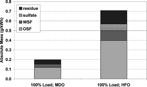
FIG. 15 Absolute masses as extracted from filters sampled at 100% load with both fuels.

FIG. 15 Absolute masses as extracted from filters sampled at 100% load with both fuels.

Reprints and Corporate Permissions

Please note: Selecting permissions does not provide access to the full text of the article, please see our help page How do I view content?

To request a reprint or corporate permissions for this article, please click on the relevant link below:

Academic Permissions

Please note: Selecting permissions does not provide access to the full text of the article, please see our help page How do I view content?

Obtain permissions instantly via Rightslink by clicking on the button below:

If you are unable to obtain permissions via Rightslink, please complete and submit this Permissions form. For more information, please visit our Permissions help page.