5,122
Views
220
CrossRef citations to date
0
Altmetric
Original Articles

An Inter-Comparison of Instruments Measuring Black Carbon Content of Soot Particles

, , , , , , , , , , , , , , , & show all
Pages 295-314 | Received 03 Mar 2006, Accepted 04 Jan 2007, Published online: 02 Mar 2007

Figures & data

TABLE 1 List of constants used in AMS-SMPS calculation of refractory mass (AL = aliphatics)

FIG. 1 Apparatus for soot production, processing, and analysis. Particles, continuously produced at the burner, flow through the system. Where the particle flow is split, sampling is performed isokinetically to avoid distortion of particle size distribution.
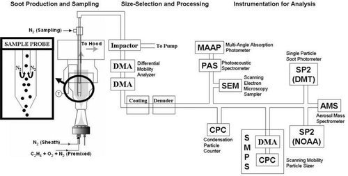
FIG. 1 Apparatus for soot production, processing, and analysis. Particles, continuously produced at the burner, flow through the system. Where the particle flow is split, sampling is performed isokinetically to avoid distortion of particle size distribution.

FIG. 2 Sample SMPS size distribution for particles produced at φ = 3.5 and selected at d m ∼ 190 nm.
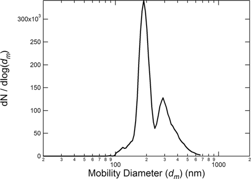
FIG. 2 Sample SMPS size distribution for particles produced at φ = 3.5 and selected at d m ∼ 190 nm.

TABLE 2 Fractional composition by mass of uncoated soot particles

FIG. 3 Scanning electron microscope (SEM) images of soot at four different equivalence ratios: φ = 2.3 (a), φ = 2.8 (b), φ = 3.5 (c), and φ = 5.0 (d).
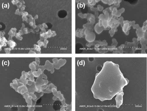
FIG. 3 Scanning electron microscope (SEM) images of soot at four different equivalence ratios: φ = 2.3 (a), φ = 2.8 (b), φ = 3.5 (c), and φ = 5.0 (d).

FIG. 4 Incandescent mass per particle measured by the SP2 instruments vs. refractory mass per particle measured by the AMS-SMPS for commercial GC spheres. The NOAA and DMT instruments are represented by different symbols.
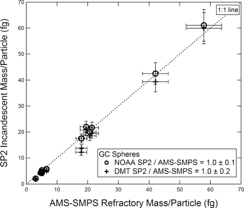
FIG. 4 Incandescent mass per particle measured by the SP2 instruments vs. refractory mass per particle measured by the AMS-SMPS for commercial GC spheres. The NOAA and DMT instruments are represented by different symbols.

FIG. 5 Incandescent mass per fractal soot particle measured by (a) the NOAA SP2 and (b) the DMT SP2, both plotted vs. refractory mass per particle measured by the AMS-SMPS. Fuel equivalence ratios are as shown in the figure.
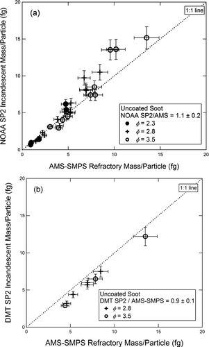
FIG. 5 Incandescent mass per fractal soot particle measured by (a) the NOAA SP2 and (b) the DMT SP2, both plotted vs. refractory mass per particle measured by the AMS-SMPS. Fuel equivalence ratios are as shown in the figure.

FIG. 6 Comparison of aerosol absorption coefficients (B abs ) measured by the MAAP vs. PAS for commercial GC spheres.
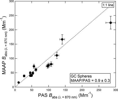
FIG. 6 Comparison of aerosol absorption coefficients (B abs ) measured by the MAAP vs. PAS for commercial GC spheres.

FIG. 7 Aerosol absorption coefficient (B abs ) for fractal soot measured by the MAAP plotted vs. the PAS. The data for lower values of B abs is expanded in (b). Fuel equivalence ratios are as shown in the figure.
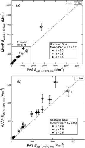
FIG. 7 Aerosol absorption coefficient (B abs ) for fractal soot measured by the MAAP plotted vs. the PAS. The data for lower values of B abs is expanded in (b). Fuel equivalence ratios are as shown in the figure.

FIG. 8 Optically absorbing mass per particle measured by the MAAP vs. PAS for commercial GC spheres.
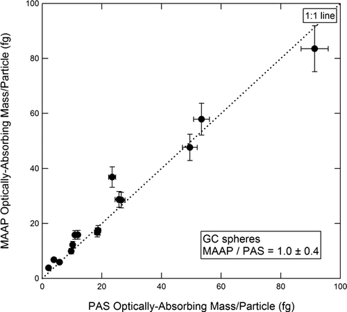
FIG. 8 Optically absorbing mass per particle measured by the MAAP vs. PAS for commercial GC spheres.

FIG. 9 Optically absorbing mass per fractal soot particle measured by the MAAP vs. the PAS. Fuel equivalence ratios are as shown in the figure.
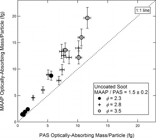
FIG. 9 Optically absorbing mass per fractal soot particle measured by the MAAP vs. the PAS. Fuel equivalence ratios are as shown in the figure.

FIG. 10 Optically absorbing mass per particle measured by the PAS (a) and MAAP (b) vs. refractory mass per particle measured by the AMS-SMPS for commercial GC spheres.
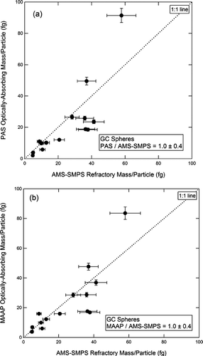
FIG. 10 Optically absorbing mass per particle measured by the PAS (a) and MAAP (b) vs. refractory mass per particle measured by the AMS-SMPS for commercial GC spheres.

FIG. 11 Optically absorbing mass per fractal soot particle measured by (a) the PAS and (b) the MAAP, both plotted vs. the refractory mass per particle measured by the AMS-SMPS. Fuel equivalence ratios are as shown in the figure.
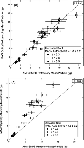
FIG. 11 Optically absorbing mass per fractal soot particle measured by (a) the PAS and (b) the MAAP, both plotted vs. the refractory mass per particle measured by the AMS-SMPS. Fuel equivalence ratios are as shown in the figure.

FIG. 12 Summary of instrument inter-comparison for GC spheres and uncoated soot. Readings are normalized to the AMS-SMPS measurements.
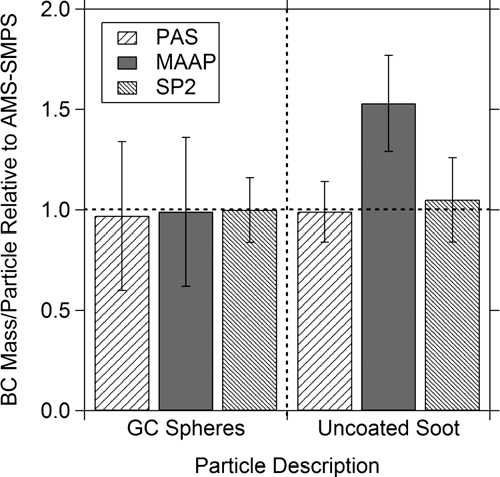
FIG. 12 Summary of instrument inter-comparison for GC spheres and uncoated soot. Readings are normalized to the AMS-SMPS measurements.

FIG. 13 AMS-SMPS measurement of refractory mass/particle for coated vs. uncoated soot. Coating materials and Δ r ve are as shown in the figure.
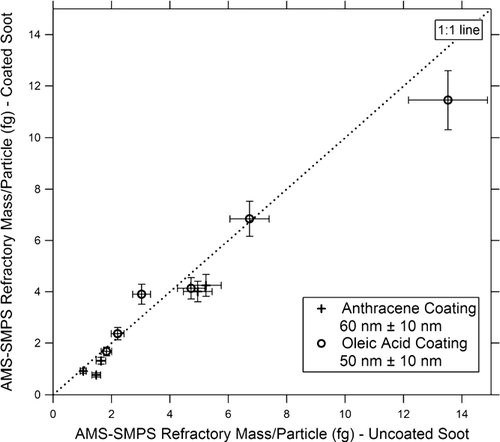
FIG. 13 AMS-SMPS measurement of refractory mass/particle for coated vs. uncoated soot. Coating materials and Δ r ve are as shown in the figure.

FIG. 14 SP2 measurement of incandescent mass/particle for coated vs. uncoated soot. Coating materials and Δ r ve are as shown in the figure. The anthracene data are obtained both from the DMT and NOAA instruments. Oleic acid data are available only from the NOAA instrument.
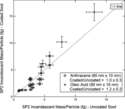
FIG. 14 SP2 measurement of incandescent mass/particle for coated vs. uncoated soot. Coating materials and Δ r ve are as shown in the figure. The anthracene data are obtained both from the DMT and NOAA instruments. Oleic acid data are available only from the NOAA instrument.

FIG. 15 MAAP measurement of optically absorbing mass/particle for coated vs. uncoated soot. Coating materials and Δ r ve are as shown in the figure.
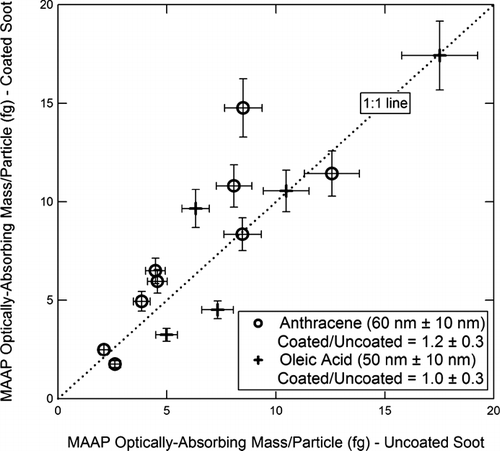
FIG. 15 MAAP measurement of optically absorbing mass/particle for coated vs. uncoated soot. Coating materials and Δ r ve are as shown in the figure.

FIG. 16 PAS measurement of optically absorbing mass/particle for coated vs. uncoated soot. Coating materials and Δ r ve are as shown in the figure. The dashed line is the best linear fit (slope 1.65) to the anthracene-coated particles.
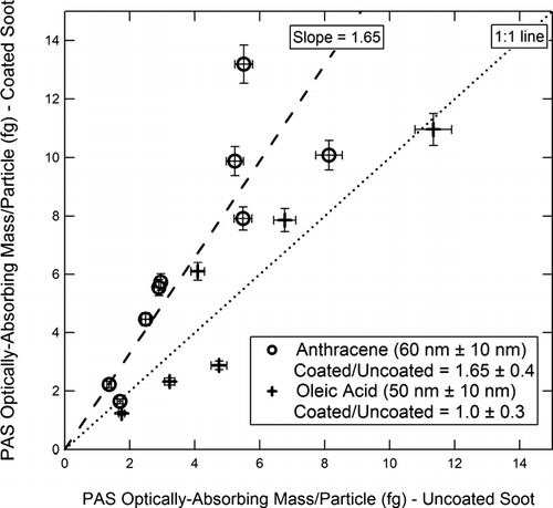
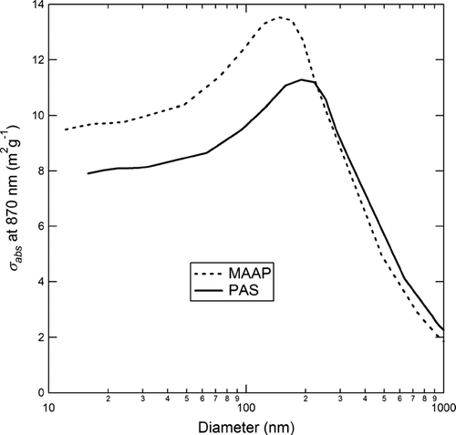
FIG. 16 PAS measurement of optically absorbing mass/particle for coated vs. uncoated soot. Coating materials and Δ r ve are as shown in the figure. The dashed line is the best linear fit (slope 1.65) to the anthracene-coated particles.

TABLE 3 BC mass per particle measured by the MAAP, PAS, and SP2 relative to the AMS-SMPS measurement for GC spheres, uncoated soot, and thick coatings of oleic acid and anthracene. Thin coatings of oleic acid and anthracene had no effect on the instrument readings.

FIG. A1 Model mass-specific absorption coefficient (σ abs ) at 870 nm measured by the MAAP and PAS as a function of particle diameter. See text for a discussion of the assumptions and methods used to generate this figure.

FIG. A1 Model mass-specific absorption coefficient (σ abs ) at 870 nm measured by the MAAP and PAS as a function of particle diameter. See text for a discussion of the assumptions and methods used to generate this figure.

Reprints and Corporate Permissions

Please note: Selecting permissions does not provide access to the full text of the article, please see our help page How do I view content?

To request a reprint or corporate permissions for this article, please click on the relevant link below:

Academic Permissions

Please note: Selecting permissions does not provide access to the full text of the article, please see our help page How do I view content?

Obtain permissions instantly via Rightslink by clicking on the button below:

If you are unable to obtain permissions via Rightslink, please complete and submit this Permissions form. For more information, please visit our Permissions help page.