1,401
Views
43
CrossRef citations to date
0
Altmetric
Original Articles

Theoretical and Experimental Evaluation of a Portable Electrostatic TEM Sampler

, &
Pages 520-528 | Received 29 Aug 2006, Accepted 31 Jan 2007, Published online: 08 May 2007

Figures & data

FIG. 1 (a) Principle of the TEM-sampler: Aerosol is charged in a Hewitt-type unipolar diffusion charger. The TEM grid is placed on a grid holder to which a negative high voltage is applied. The grid is held in place with a cap (shown in black). Charged particles are deposited on the TEM grid by electrostatic force, and remaining particles are measured in an aerosol electrometer. (b) Detail view of the sampling zone.
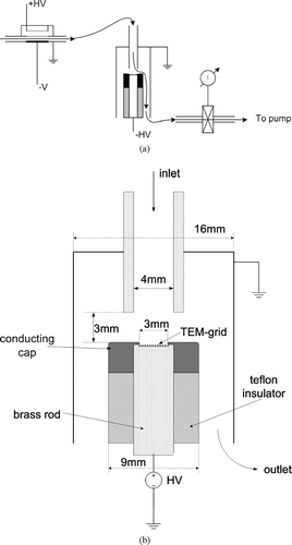
FIG. 1 (a) Principle of the TEM-sampler: Aerosol is charged in a Hewitt-type unipolar diffusion charger. The TEM grid is placed on a grid holder to which a negative high voltage is applied. The grid is held in place with a cap (shown in black). Charged particles are deposited on the TEM grid by electrostatic force, and remaining particles are measured in an aerosol electrometer. (b) Detail view of the sampling zone.

FIG. 2 Geometry of the Sampler and flow streamlines. The geometry has a rotational symmetry around the axis x = 0 mm. The TEM grid is placed on the grid holder in the y = 0 mm plane, and held in place by the cap (shown in black). The thick line is the trajectory of a particle of 50 nm diameter with one elementary charge released at r = Rc.
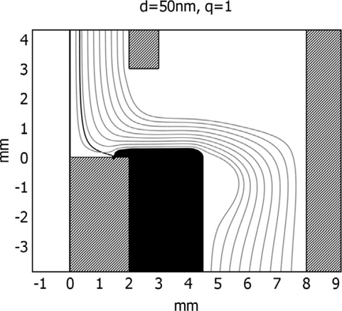
FIG. 2 Geometry of the Sampler and flow streamlines. The geometry has a rotational symmetry around the axis x = 0 mm. The TEM grid is placed on the grid holder in the y = 0 mm plane, and held in place by the cap (shown in black). The thick line is the trajectory of a particle of 50 nm diameter with one elementary charge released at r = Rc.

TABLE 1 Sampling efficiency for different particle diameters and number of charges. For larger particles and small charge levels, the efficiency was not computed, since these charge levels are unlikely for our charger

TABLE 2 Measured average charge per particle, calculated and measured sampling efficiency

FIG. 3 Particle trajectories and equipotential lines of the electric potential. Deposition of 50 nm particles released at starting points r = i*r0, i = 0 …10 is uniform on the substrate.
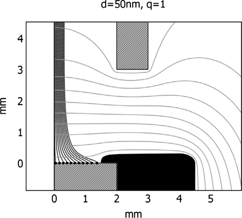
FIG. 3 Particle trajectories and equipotential lines of the electric potential. Deposition of 50 nm particles released at starting points r = i*r0, i = 0 …10 is uniform on the substrate.

FIG. 4 Particles with a diameter of 5 nm are focused on the center of the TEM grid. The cones represent the velocity field of the gas flow.
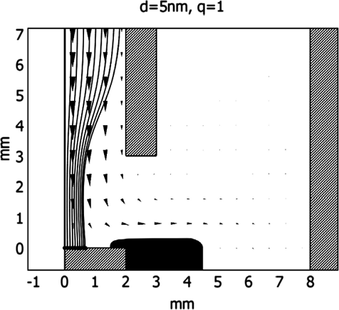
FIG. 4 Particles with a diameter of 5 nm are focused on the center of the TEM grid. The cones represent the velocity field of the gas flow.

FIG. 5 Profile through a TEM grid. The stars indicate the number of particles detected on the corresponding mesh. The x-axis corresponds to the location of the profile. The numbers indicate the meshes on which the particles have been counted. A part of the grid is covered by the grid holder.
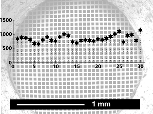
FIG. 5 Profile through a TEM grid. The stars indicate the number of particles detected on the corresponding mesh. The x-axis corresponds to the location of the profile. The numbers indicate the meshes on which the particles have been counted. A part of the grid is covered by the grid holder.

FIG. 6 Experimental setup for the generation of polydisperse (left) and monodisperse (right) aerosols.
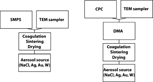
FIG. 6 Experimental setup for the generation of polydisperse (left) and monodisperse (right) aerosols.

FIG. 7 Typical TEM bright field image of polydisperse Ag particles.

FIG. 7 Typical TEM bright field image of polydisperse Ag particles.

FIG. 8 Calibration curve for the TEM sampler covering the size range from 20–320 nm. Crosses: measurements; circles: mean of measurements for a given size; stars: model calculations.
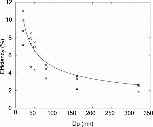
FIG. 8 Calibration curve for the TEM sampler covering the size range from 20–320 nm. Crosses: measurements; circles: mean of measurements for a given size; stars: model calculations.

FIG. 9 (a) Comparison of SMPS measurements with results derived from TEM-IA for polydisperse Ag particles. Dashed line: SMPS measurements (N = 4.5 × 10⁶ particles/cm3, geometric mean = 47.7 nm). Solid line: TEM-IA results (N = 4.6 × 10⁶ particles/cm3, geometric mean = 43.7 nm). (b) Comparison of SMPS measurements with results derived from TEM-IA for polydisperse Au particles. Dashed line: SMPS measurements (N = 1.3 × 10⁷ particles/cm3, geometric mean = 23.8 nm). Solid line: TEM-IA results (N = 7.9 × 10⁶ particles/cm3, geometric mean = 24.1 nm).
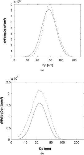
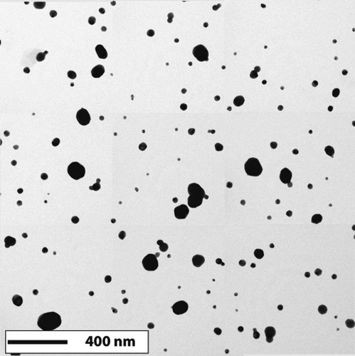
FIG. 9 (a) Comparison of SMPS measurements with results derived from TEM-IA for polydisperse Ag particles. Dashed line: SMPS measurements (N = 4.5 × 10⁶ particles/cm3, geometric mean = 47.7 nm). Solid line: TEM-IA results (N = 4.6 × 10⁶ particles/cm3, geometric mean = 43.7 nm). (b) Comparison of SMPS measurements with results derived from TEM-IA for polydisperse Au particles. Dashed line: SMPS measurements (N = 1.3 × 10⁷ particles/cm3, geometric mean = 23.8 nm). Solid line: TEM-IA results (N = 7.9 × 10⁶ particles/cm3, geometric mean = 24.1 nm).

Reprints and Corporate Permissions

Please note: Selecting permissions does not provide access to the full text of the article, please see our help page How do I view content?

To request a reprint or corporate permissions for this article, please click on the relevant link below:

Academic Permissions

Please note: Selecting permissions does not provide access to the full text of the article, please see our help page How do I view content?

Obtain permissions instantly via Rightslink by clicking on the button below:

If you are unable to obtain permissions via Rightslink, please complete and submit this Permissions form. For more information, please visit our Permissions help page.