1,117
Views
8
CrossRef citations to date
0
Altmetric
Original Articles

Unipolar Field and Diffusion Charging in the Transition Regime—Part II: Charging Experiments

, &
Pages 611-623 | Received 03 Sep 2006, Accepted 09 Feb 2007, Published online: 16 May 2007

Figures & data

FIG. 1 Corona charger (wire-tube ESP design). Flow direction and sampling positions 1 to 6 as indicated, with Pos. 3 to 6 optional. Active corona length Lc limited by shielding tubes of different lengths at both ends (bold: Lc = 24 cm; open: Lc = 5 cm). Light gray areas: insulating material (PVC); dark gray: metal.

FIG. 1 Corona charger (wire-tube ESP design). Flow direction and sampling positions 1 to 6 as indicated, with Pos. 3 to 6 optional. Active corona length Lc limited by shielding tubes of different lengths at both ends (bold: Lc = 24 cm; open: Lc = 5 cm). Light gray areas: insulating material (PVC); dark gray: metal.

FIG. 2 Radial ion concentration profiles n i (r) in the core zone (Lcore ≈ 22 cm) of the charger calculated for three pairs of corona current and voltage (Lc = 24 cm, Rtube = 2 cm; Rwire = 0.05 cm; ion mobility Zi = 1.4 · 10− 4 m2/Vs).
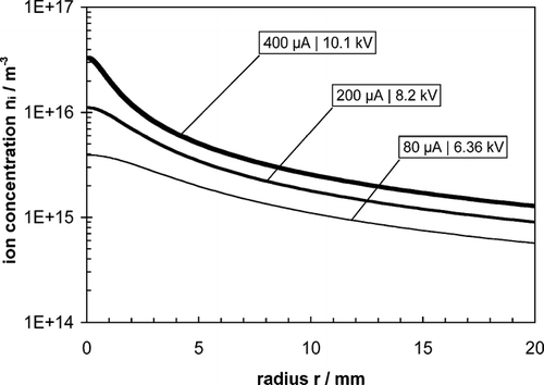
FIG. 2 Radial ion concentration profiles n i (r) in the core zone (Lcore ≈ 22 cm) of the charger calculated for three pairs of corona current and voltage (Lc = 24 cm, Rtube = 2 cm; Rwire = 0.05 cm; ion mobility Zi = 1.4 · 10− 4 m2/Vs).

FIG. 3 Radial profiles of the electric field E0(r) with and without the effect of space charge, calculated for two pairs of corona current and voltage in the core zone (Lcore≈ 22 cm) of the charger (Lc = 24 cm; Rtube = 2 cm; Rwire = 0.05 cm; ion mobility Zi = 1.4 · 10− 4 m2/Vs).
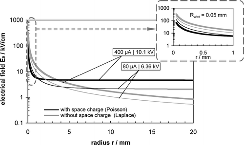
FIG. 3 Radial profiles of the electric field E0(r) with and without the effect of space charge, calculated for two pairs of corona current and voltage in the core zone (Lcore≈ 22 cm) of the charger (Lc = 24 cm; Rtube = 2 cm; Rwire = 0.05 cm; ion mobility Zi = 1.4 · 10− 4 m2/Vs).

FIG. 4 Average charge versus n· t product for different particle sizes and E-fields. Here n· t is varied only via the corona intensity and the E-field. Solid lines represent the Fuchs diffusion charging model (qP); data points are measured values qexit.
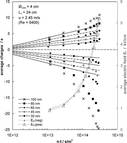
FIG. 4 Average charge versus n· t product for different particle sizes and E-fields. Here n· t is varied only via the corona intensity and the E-field. Solid lines represent the Fuchs diffusion charging model (qP); data points are measured values qexit.
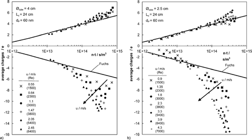
FIG. 5 Average charge vs. n· t product for a fixed particle size of 60 nm and two different charger diameters (left 4 cm and right 2.5 cm). Here n· t is varied via the corona intensity and the flow velocity. Solid lines represent the Fuchs diffusion charging model (qP); data points are measured values qexit.

FIG. 5 Average charge vs. n· t product for a fixed particle size of 60 nm and two different charger diameters (left 4 cm and right 2.5 cm). Here n· t is varied via the corona intensity and the flow velocity. Solid lines represent the Fuchs diffusion charging model (qP); data points are measured values qexit.

FIG. 6 Average charge vs. n· t product for 60 nm particles size at fixed flow Re number. Here n· t is varied via corona intensity. Thin lines are qp/e calculated according to the field-diffusion charging model described in Part I; data points are measured values qexit.
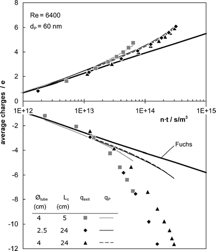
FIG. 6 Average charge vs. n· t product for 60 nm particles size at fixed flow Re number. Here n· t is varied via corona intensity. Thin lines are qp/e calculated according to the field-diffusion charging model described in Part I; data points are measured values qexit.

FIG. 7 Charging kinetics of 60 nm aerosol at fixed electric conditions; n· t-variation via charging time (sampling at different wall positions; lines calculated according to combined field and diffusion charging theory (model from Part I).
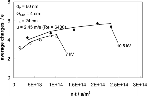
FIG. 7 Charging kinetics of 60 nm aerosol at fixed electric conditions; n· t-variation via charging time (sampling at different wall positions; lines calculated according to combined field and diffusion charging theory (model from Part I).

FIG. 8 Relative deviation between predicted (qP) and measured (qexit) charge versus measured particle charge for different particle size; n· t is varied only via the corona intensity. The model is calculated according to Part I. Gray dashed lines: range of estimated experimental error. (a) Large charger tube Øtube = 4 cm. (b) Small charger tube Øtube = 2.5 cm.
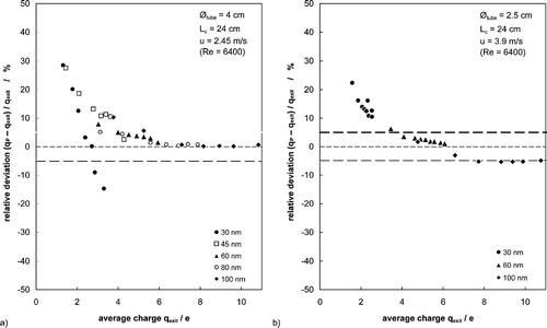
FIG. 8 Relative deviation between predicted (qP) and measured (qexit) charge versus measured particle charge for different particle size; n· t is varied only via the corona intensity. The model is calculated according to Part I. Gray dashed lines: range of estimated experimental error. (a) Large charger tube Øtube = 4 cm. (b) Small charger tube Øtube = 2.5 cm.

FIG. 9 Particle losses in the charger for positive and negative corona, compared to theoretical limiting cases for complete radial mixing (Deutsch model) and laminar flow (charger tube Øtube = 4 cm). (a) Positive and (b) negative polarity.

FIG. 9 Particle losses in the charger for positive and negative corona, compared to theoretical limiting cases for complete radial mixing (Deutsch model) and laminar flow (charger tube Øtube = 4 cm). (a) Positive and (b) negative polarity.

FIG. 10 Particle losses in the charger for positive and negative corona, compared to theoretical limiting cases for complete radial mixing (Deutsch model) and laminar flow (charger tube Øtube = 2.5 cm). (a) Positive and (b) negative polarity.

FIG. 10 Particle losses in the charger for positive and negative corona, compared to theoretical limiting cases for complete radial mixing (Deutsch model) and laminar flow (charger tube Øtube = 2.5 cm). (a) Positive and (b) negative polarity.

FIG. 11 Particle losses versus particle charge attained in the charger for two series with low and high Reynolds number.
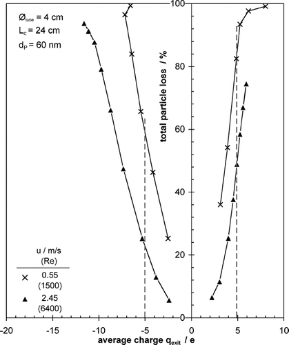
FIG. 11 Particle losses versus particle charge attained in the charger for two series with low and high Reynolds number.

FIG. 12 Relative deviation between predicted (qP) and measured (qexit) charge vs. measured particle charge for different particle size; n· t is varied only via the corona intensity. Evaluation contrary to here with an ion mobility of Zi = 1.68 m2/Vs. Gray dashed lines: range of estimated experimental error.
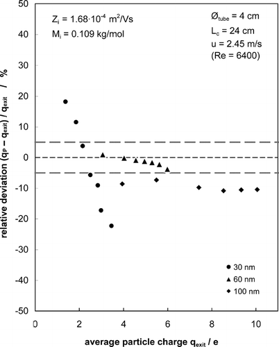
FIG. 12 Relative deviation between predicted (qP) and measured (qexit) charge vs. measured particle charge for different particle size; n· t is varied only via the corona intensity. Evaluation contrary to Figure 8a here with an ion mobility of Zi = 1.68 m2/Vs. Gray dashed lines: range of estimated experimental error.

Reprints and Corporate Permissions

Please note: Selecting permissions does not provide access to the full text of the article, please see our help page How do I view content?

To request a reprint or corporate permissions for this article, please click on the relevant link below:

Academic Permissions

Please note: Selecting permissions does not provide access to the full text of the article, please see our help page How do I view content?

Obtain permissions instantly via Rightslink by clicking on the button below:

If you are unable to obtain permissions via Rightslink, please complete and submit this Permissions form. For more information, please visit our Permissions help page.