1,148
Views
10
CrossRef citations to date
0
Altmetric
Original Articles

Thermophoretic Sampler and its Application in Ultrafine Particle Collection

&
Pages 624-629 | Received 25 Sep 2006, Accepted 09 Feb 2007, Published online: 16 May 2007

Figures & data

FIG. 1 Schematic of collection region of thermophoretic sampler. L, W and h are the sampler's length, width, and the gap between hot and cold plates. Air inlet flow velocity is V f , the thermophoretic velocity is V th with V th1 and V th2 standing for thermophoretic velocity in the L 1 and L 2 region. T c and T h are cold-and hot-side surface temperatures with T h1 and T h2 standing for the hot side temperature in the L 1 and L 2 region. The temperature gradient in the L 1 and L 2 region are ∇ T 1 = T h1T c /h and ∇ T 2 = T h2T c /h, respectively.

FIG. 1 Schematic of collection region of thermophoretic sampler. L, W and h are the sampler's length, width, and the gap between hot and cold plates. Air inlet flow velocity is V f , the thermophoretic velocity is V th with V th1 and V th2 standing for thermophoretic velocity in the L 1 and L 2 region. T c and T h are cold-and hot-side surface temperatures with T h1 and T h2 standing for the hot side temperature in the L 1 and L 2 region. The temperature gradient in the L 1 and L 2 region are ∇ T 1 = T h1− T c /h and ∇ T 2 = T h2 − T c /h, respectively.
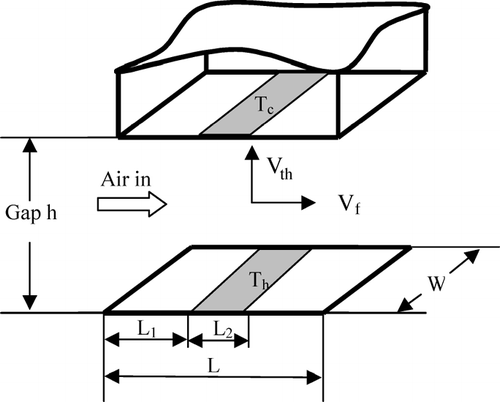
FIG. 2 Section view of designed thermophoretic sampler. The gap between the cold and hot side of collection area is 0.1 mm, and a bypass flow channel is introduced to reduce diffusional particle loss.
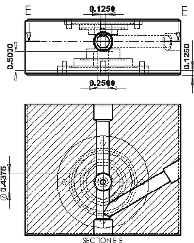
FIG. 2 Section view of designed thermophoretic sampler. The gap between the cold and hot side of collection area is 0.1 mm, and a bypass flow channel is introduced to reduce diffusional particle loss.

FIG. 3 Theoretical estimation of total particle collection efficiency as a function of thermophoretic flow rate at inlet flow rate, q vtube , of 2 lpm for particle diameters of 1 and 5 nm.

FIG. 3 Theoretical estimation of total particle collection efficiency as a function of thermophoretic flow rate at inlet flow rate, q v − tube , of 2 lpm for particle diameters of 1 and 5 nm.
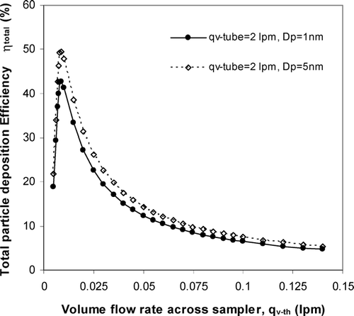
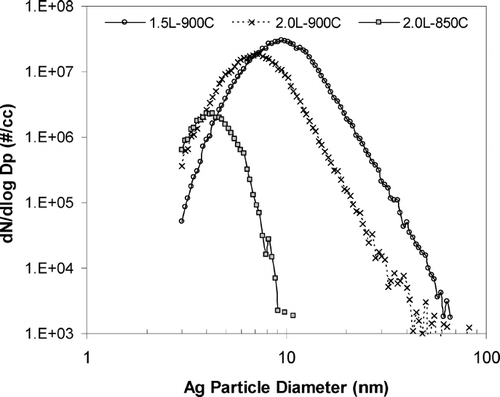
FIG. 4 Number distributions of Ag particle generated by a homogeneous condensation aerosol generator. The furnace temperature and inlet flow rate are set at 850 and 900°C, and 1.5 and 2 liters, respectively. Note that particle size is shifted to less than 10 nm when furnace temperature is lowered.

FIG. 4 Number distributions of Ag particle generated by a homogeneous condensation aerosol generator. The furnace temperature and inlet flow rate are set at 850 and 900°C, and 1.5 and 2 liters, respectively. Note that particle size is shifted to less than 10 nm when furnace temperature is lowered.

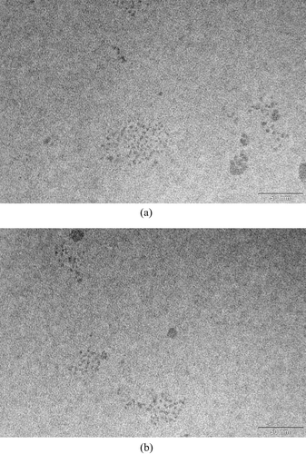
FIG. 5 Ag particles deposited on the transmission electron microscope grid at two different grid locations. The sampling inlet flowrate is 2 lpm, thermophoretic flowrate is 0.015 lpm, temperature gradient is 4.7 × 10⁵ K/m, and the sampling time is 90 minutes.

FIG. 5 Ag particles deposited on the transmission electron microscope grid at two different grid locations. The sampling inlet flowrate is 2 lpm, thermophoretic flowrate is 0.015 lpm, temperature gradient is 4.7 × 10⁵ K/m, and the sampling time is 90 minutes.

Reprints and Corporate Permissions

Please note: Selecting permissions does not provide access to the full text of the article, please see our help page How do I view content?

To request a reprint or corporate permissions for this article, please click on the relevant link below:

Academic Permissions

Please note: Selecting permissions does not provide access to the full text of the article, please see our help page How do I view content?

Obtain permissions instantly via Rightslink by clicking on the button below:

If you are unable to obtain permissions via Rightslink, please complete and submit this Permissions form. For more information, please visit our Permissions help page.