947
Views
38
CrossRef citations to date
0
Altmetric
Original Articles

A Newly Designed and Constructed Instrument for Coupled Infrared Extinction and Size Distribution Measurements of Aerosols

, , , &
Pages 701-710 | Received 09 Aug 2006, Accepted 18 Apr 2007, Published online: 06 Jun 2007

Figures & data

FIG. 1 The main components of the Multi-Analysis Aerosol Reactor System (MAARS) designed to simultaneously measure aerosols IR extinction spectra and size distributions as a function of mobility and aerodynamic diameter with an SMPS and APS, respectively, are shown. A detailed view of the IR observation tube is shown with physical lengths for the glass tube, distance between window purges and aerosol stream in and out ports. See text for further detail.
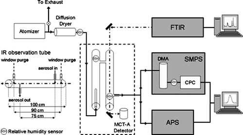
FIG. 1 The main components of the Multi-Analysis Aerosol Reactor System (MAARS) designed to simultaneously measure aerosols IR extinction spectra and size distributions as a function of mobility and aerodynamic diameter with an SMPS and APS, respectively, are shown. A detailed view of the IR observation tube is shown with physical lengths for the glass tube, distance between window purges and aerosol stream in and out ports. See text for further detail.

FIG. 2 The average size distribution, with respect to mobility diameter, of 701 ± 6 nm polystyrene latex spheres (PSLs) measured by the SMPS (open bars) and APS (hatched bars). The APS data has been adjusted to mobility diameter according to Equation (Equation1) using ρp = 1.05 g cm−3 and χ = 1. The error bars represent the standard deviation on the average value of five measurements.
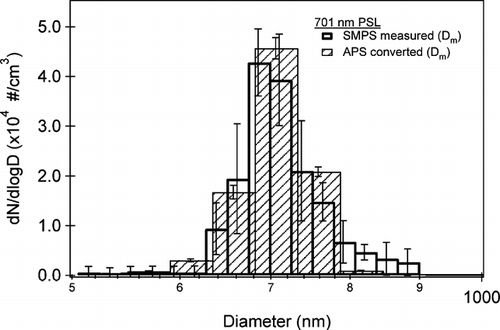
FIG. 2 The average size distribution, with respect to mobility diameter, of 701 ± 6 nm polystyrene latex spheres (PSLs) measured by the SMPS (open bars) and APS (hatched bars). The APS data has been adjusted to mobility diameter according to Equation (Equation1) using ρp = 1.05 g cm−3 and χ = 1. The error bars represent the standard deviation on the average value of five measurements.

FIG. 3 (a) A partial size distribution of ammonium sulfate showing the overlap region between the SMPS (open diamonds) and APS. The APS data are shown as a function of aerodynamic diameter (filled circles) and adjusted to mobility diameter (plusses) according to Equation (Equation3). Using a density ρp = 1.769 g cm−3, a dynamic shape factor is calculated, χ = 1.01. The process of overlapping the SMPS and APS is discussed in detail in the text. (b) The full size distribution of ammonium sulfate on a log scale from 10 to 2000 nm. The size distributions are shown as a function of mobility diameter (Dm) and volume equivalent diameter (Dve). The dotted box highlights the overlap region between the SMPS and APS shown in . (c) SEM image of ammonium sulfate collected in the particle stream. The small particles, < 200 nm, are spherical where as larger particles can deviate in shape from that of a sphere.
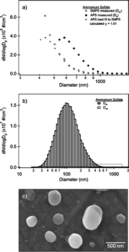
FIG. 3 (a) A partial size distribution of ammonium sulfate showing the overlap region between the SMPS (open diamonds) and APS. The APS data are shown as a function of aerodynamic diameter (filled circles) and adjusted to mobility diameter (plusses) according to Equation (Equation3). Using a density ρp = 1.769 g cm−3, a dynamic shape factor is calculated, χ = 1.01. The process of overlapping the SMPS and APS is discussed in detail in the text. (b) The full size distribution of ammonium sulfate on a log scale from 10 to 2000 nm. The size distributions are shown as a function of mobility diameter (Dm) and volume equivalent diameter (Dve). The dotted box highlights the overlap region between the SMPS and APS shown in Figure 3a. (c) SEM image of ammonium sulfate collected in the particle stream. The small particles, < 200 nm, are spherical where as larger particles can deviate in shape from that of a sphere.

FIG. 4 (a) The experimental IR spectrum (black line) acquired simultaneously with the size distribution shown in and a Mie simulation (dotted line) using the CitationToon et al. (1976) ammonium sulfate optical constants and the measured size distribution. The area of the ammonium region (integrated from 2500 to 3700 cm−1) from the Mie simulation has been matched to that of the experimental spectrum to determine the path length of the IR cell. The path length for this spectrum was found to be 78 cm in good agreement with the experimental setup. b) The difference between the two spectra (Mie simulation—experimental). The ν3(NH4 +) peak in the Mie simulation is red shifted 44 cm−1 relative to the experimental spectrum. The largest differences are observed in the peak height of the ν3(SO4 2−) and ν4(NH4 +) peaks. The ratio of the peak area of these peaks between the Mie simulation and experimental spectrum are within 10%. These are also slightly shifted (10 cm−1) in the Mie simulation relative to the experimental spectrum.
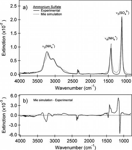
FIG. 4 (a) The experimental IR spectrum (black line) acquired simultaneously with the size distribution shown in Figure 3b and a Mie simulation (dotted line) using the CitationToon et al. (1976) ammonium sulfate optical constants and the measured size distribution. The area of the ammonium region (integrated from 2500 to 3700 cm−1) from the Mie simulation has been matched to that of the experimental spectrum to determine the path length of the IR cell. The path length for this spectrum was found to be 78 cm in good agreement with the experimental setup. b) The difference between the two spectra (Mie simulation—experimental). The ν3(NH4 +) peak in the Mie simulation is red shifted 44 cm−1 relative to the experimental spectrum. The largest differences are observed in the peak height of the ν3(SO4 2−) and ν4(NH4 +) peaks. The ratio of the peak area of these peaks between the Mie simulation and experimental spectrum are within 10%. These are also slightly shifted (10 cm−1) in the Mie simulation relative to the experimental spectrum.

FIG. 5 (a) A partial size distribution of illite showing the overlap region between the SMPS (open diamonds) and APS. The APS data are shown as a function of aerodynamic diameter (filled circles) and adjusted to mobility diameter (plusses) according to Equation (Equation3). Using a density ρp = 2.8 g cm−3, a dynamic shape factor is calculated, χ = 1.30. The process of overlapping the SMPS and APS is discussed in detail in the text. (b) The full size distribution of illite on a log scale from 10 to 2000 nm. The size distributions are shown as a function of mobility diameter (Dm) and volume equivalent diameter (Dve). The dotted box highlights the overlap region between the SMPS and APS shown in . (c) SEM image of illite collected in the particle stream. The illite particles appear plate-like supporting the large value of the experimentally determined χ.
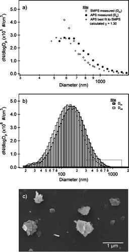
FIG. 5 (a) A partial size distribution of illite showing the overlap region between the SMPS (open diamonds) and APS. The APS data are shown as a function of aerodynamic diameter (filled circles) and adjusted to mobility diameter (plusses) according to Equation (Equation3). Using a density ρp = 2.8 g cm−3, a dynamic shape factor is calculated, χ = 1.30. The process of overlapping the SMPS and APS is discussed in detail in the text. (b) The full size distribution of illite on a log scale from 10 to 2000 nm. The size distributions are shown as a function of mobility diameter (Dm) and volume equivalent diameter (Dve). The dotted box highlights the overlap region between the SMPS and APS shown in Figure 5a. (c) SEM image of illite collected in the particle stream. The illite particles appear plate-like supporting the large value of the experimentally determined χ.

FIG. 6 (a) Experimental IR spectrum (black line) acquired simultaneously with the size distribution shown in and a Mie simulation (dotted line) using the CitationQuerry (1987) optical constants for illite and the volume equivalent diameter size distribution (Dve). The peaks identified are for the Al—Al—OH deformation at 916 cm−1, the ν (Si—O) at 1036 cm−1 and the inner OH stretch at 3616 cm−1. Some gas-phase CO2 and H2O absorptions are observed in the experimental spectrum. Key differences between the simulations and the experimental spectrum are seen in the slope of the baseline from 2500–3500 cm−1 and a blue shift of the ν (Si—O) at 1036 cm−1 to 1080 cm−1 in the Mie simulations relative to the experimental spectrum. (b) An expansion of the IR spectrum for the two spectra in from 850 to 1350 cm−1. The experimental peaks and shoulder are underlined for clarity. A small blue shift in the position of the Al—Al—OH deformation of the Mie simulation can also be seen. (c) The difference between the Mie simulation and the experimental spectrum for the spectral range from 850–4000 cm−1. The largest difference is observed between the peak positions of the ν (Si—O) in the resonance region.
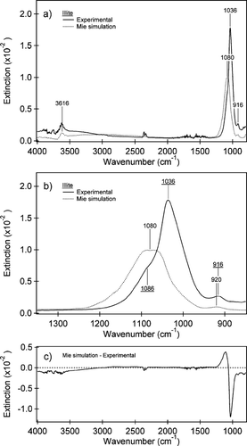
FIG. 6 (a) Experimental IR spectrum (black line) acquired simultaneously with the size distribution shown in Figure 5b and a Mie simulation (dotted line) using the CitationQuerry (1987) optical constants for illite and the volume equivalent diameter size distribution (Dve). The peaks identified are for the Al—Al—OH deformation at 916 cm−1, the ν (Si—O) at 1036 cm−1 and the inner OH stretch at 3616 cm−1. Some gas-phase CO2 and H2O absorptions are observed in the experimental spectrum. Key differences between the simulations and the experimental spectrum are seen in the slope of the baseline from 2500–3500 cm−1 and a blue shift of the ν (Si—O) at 1036 cm−1 to 1080 cm−1 in the Mie simulations relative to the experimental spectrum. (b) An expansion of the IR spectrum for the two spectra in Figure 6a from 850 to 1350 cm−1. The experimental peaks and shoulder are underlined for clarity. A small blue shift in the position of the Al—Al—OH deformation of the Mie simulation can also be seen. (c) The difference between the Mie simulation and the experimental spectrum for the spectral range from 850–4000 cm−1. The largest difference is observed between the peak positions of the ν (Si—O) in the resonance region.

Reprints and Corporate Permissions

Please note: Selecting permissions does not provide access to the full text of the article, please see our help page How do I view content?

To request a reprint or corporate permissions for this article, please click on the relevant link below:

Academic Permissions

Please note: Selecting permissions does not provide access to the full text of the article, please see our help page How do I view content?

Obtain permissions instantly via Rightslink by clicking on the button below:

If you are unable to obtain permissions via Rightslink, please complete and submit this Permissions form. For more information, please visit our Permissions help page.