Figures & data
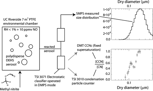
FIG. 1 Schematic of measurement strategy. The two figures on the right show an example size distribution and CCN activation data for a single experiment. Vertical bars in the bottom figure represent ±2 standard deviations, computed from ∼60 independent data points.

FIG. 2 Calculated CCNc response curve (thick solid line, right ordinate, as function of mobility selected diameter) for log-normally distributed, charge-equilibrated particles transmitted through an ideal DMA followed by transit through an ideal CCN instrument. Shown are an assumed log-normal input size distribution (solid line, left ordinate, N = 900 cm−3, D g = 0.14 μm, s g = 1.33), the ratio of [+2]/[+1] (dashed line) and [+3]/[+1] (dashed-dotted line) charges at charge equilibrium (right ordinate), the assumed critical diameter for the model calculations (dotted line), the centroid sphere equivalent mobility diameter, and the mobility band-width for +1, +2, and +3 (from left to right) charged particles transmitted through the TSI long DMA column at an assumed 10:2 sheath-to-monodisperse flow ratio (gray intervals).
![FIG. 2 Calculated CCNc response curve (thick solid line, right ordinate, as function of mobility selected diameter) for log-normally distributed, charge-equilibrated particles transmitted through an ideal DMA followed by transit through an ideal CCN instrument. Shown are an assumed log-normal input size distribution (solid line, left ordinate, N = 900 cm−3, D g = 0.14 μm, s g = 1.33), the ratio of [+2]/[+1] (dashed line) and [+3]/[+1] (dashed-dotted line) charges at charge equilibrium (right ordinate), the assumed critical diameter for the model calculations (dotted line), the centroid sphere equivalent mobility diameter, and the mobility band-width for +1, +2, and +3 (from left to right) charged particles transmitted through the TSI long DMA column at an assumed 10:2 sheath-to-monodisperse flow ratio (gray intervals).](/cms/asset/4730ed2d-1e8c-423d-a8ab-73a1d71ab59b/uast_a_255579_o_f0002g.gif)
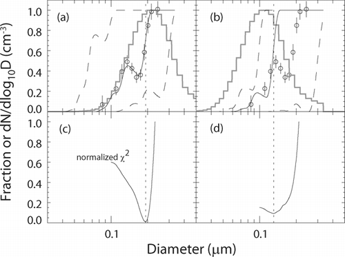
FIG. 3 Panels (a, b): Measured CCNc response (circles) for DEHS+OH experiment at S = 0.64%. Vertical bars represent ±2 standard deviations, computed from ∼60 independent data points. Gray histogram, panel a: normalized spectral density of the input size distribution. Gray histogram, panel b: same as figure a, but the mode diameter is shifted by ∼0.1 μm toward smaller sizes. Dashed and solid lines, panels a, b: Calculated CCNc response curves for various assumed D c (see text). Panels c, d: Normalized χ2-statistic as a function of assumed values of D c . The minimum value (dotted line) is used to determine the best-fit CCNc response curve.

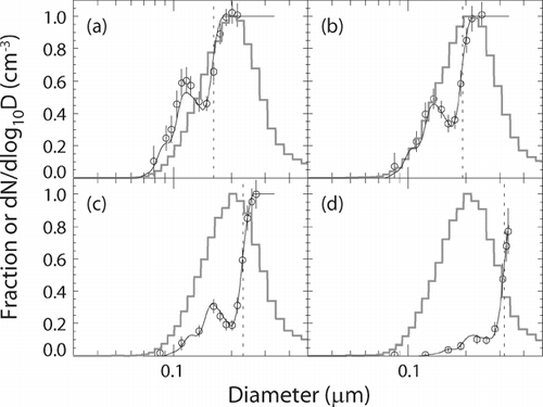
FIG. 4 Measured CCNc response (circles) for DEHS+OH experiment; (a) S = 0.75%, (b) S = 0.64%, (c) S = 0.53%, (d) S = 0.33%. Vertical bars represent ±2 standard deviations, computed from ∼60 independent data points. Gray histogram: normalized spectral density of the input size distribution. Solid line: best-fit CCNc response curve. The critical diameter yielding the best fit to the observation is indicated by the dotted line; (a) D c = 0.16 μm, (b) D c = 0.19 μm, (c) D c = 0.23 μm, (d) D c = 0.32 μm.
