944
Views
17
CrossRef citations to date
0
Altmetric
Original Articles

Single-Fiber Interception Efficiency for Elliptical Fibers

Pages 357-368 | Received 12 Oct 2007, Accepted 04 Apr 2008, Published online: 28 May 2008

Figures & data

FIG. 1 Illustration of particle interception by a circular cross-section fiber with radius df/2. A particle follows the limiting streamline shown until it contacts the fiber at an angle of 90° relative to the incoming flow. The distance from the centerline to the point that the limiting streamline enters the solution domain, yc, divided by df/2 is the single fiber interception efficiency in this case.
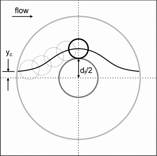
FIG. 1 Illustration of particle interception by a circular cross-section fiber with radius df/2. A particle follows the limiting streamline shown until it contacts the fiber at an angle of 90° relative to the incoming flow. The distance from the centerline to the point that the limiting streamline enters the solution domain, yc, divided by df/2 is the single fiber interception efficiency in this case.

FIG. 2 Diagram of solution domain having a solidity of 0.04 for a fiber with an elliptical cross-section having an aspect ratio of 2.5. The elliptical coordinate system is superimposed on the solution domain. Curves of constant χ are ellipses whereas curves of constant φ are hyperbolas. The surface of the fiber and the outer boundary of the solution domain are indicated as having values of χf and χc, respectively.
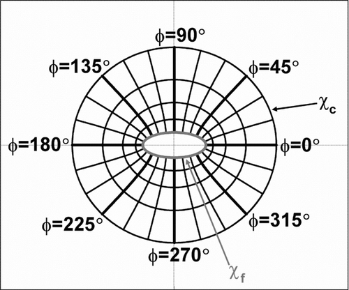
FIG. 2 Diagram of solution domain having a solidity of 0.04 for a fiber with an elliptical cross-section having an aspect ratio of 2.5. The elliptical coordinate system is superimposed on the solution domain. Curves of constant χ are ellipses whereas curves of constant φ are hyperbolas. The surface of the fiber and the outer boundary of the solution domain are indicated as having values of χf and χc, respectively.

FIG. 3 Illustration of particle interception by elliptical cross-section fibers with the major axis of their cross-sections oriented at (a) 90°, (b) 45°, and (c) 0° to the incoming flow. A circle with radius (lfwf).5ex1−.1em/−.15em.25ex2/2, which has an area equal to the area of the elliptical cross-section, is superimposed on each figure. The particle follows the limiting streamline shown until it contacts the fiber. The starting point of the limiting streamline and the position on the cross-section where the particle contacts the fiber vary with the angle of orientation. The distance from the centerline that the limiting streamline enters the solution domain—y90, y45, or y0—divided by (lfwf).5ex 1−.1em/−.15em.25ex 2/2 is the single fiber interception efficiency in these cases.
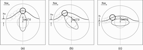
FIG. 3 Illustration of particle interception by elliptical cross-section fibers with the major axis of their cross-sections oriented at (a) 90°, (b) 45°, and (c) 0° to the incoming flow. A circle with radius (lfwf).5ex1−.1em/−.15em.25ex2/2, which has an area equal to the area of the elliptical cross-section, is superimposed on each figure. The particle follows the limiting streamline shown until it contacts the fiber. The starting point of the limiting streamline and the position on the cross-section where the particle contacts the fiber vary with the angle of orientation. The distance from the centerline that the limiting streamline enters the solution domain—y90, y45, or y0—divided by (lfwf).5ex 1−.1em/−.15em.25ex 2/2 is the single fiber interception efficiency in these cases.

FIG. 4 Surfaces and curves used to calculate single-fiber interception efficiency. The R* -distant curve is everywhere a distance R* from the fiber surface. The normal lines are normal to both the fiber surface and the R* -distant curve and connect points on the R* -distant curve to the corresponding closest points on the fiber surface. The limiting streamline intersects the R* -distant curve at only one point. The particle is shown at the location on the limiting streamline where it is intercepted by the fiber.
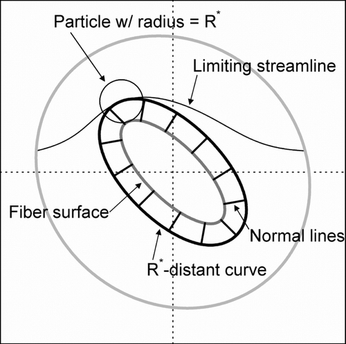
FIG. 4 Surfaces and curves used to calculate single-fiber interception efficiency. The R* -distant curve is everywhere a distance R* from the fiber surface. The normal lines are normal to both the fiber surface and the R* -distant curve and connect points on the R* -distant curve to the corresponding closest points on the fiber surface. The limiting streamline intersects the R* -distant curve at only one point. The particle is shown at the location on the limiting streamline where it is intercepted by the fiber.

TABLE 1 Independent variables and their values for which single-fiber interception efficiency was computed numerically in a factorial design

FIG. 5 The logarithm of single-fiber interception efficiency predicted using empirically developed Equation (Equation32) plotted against the logarithm of interception efficiency computed using numerical methods.
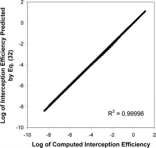
FIG. 5 The logarithm of single-fiber interception efficiency predicted using empirically developed Equation (Equation32) plotted against the logarithm of interception efficiency computed using numerical methods.

FIG. 6 Single-fiber interception efficiency versus particle diameter for several orientation angles. In all cases, aspect ratio is 6, solidity is 0.016, and the cross-sectional area is equivalent to that of a circular fiber with a 3 μ m diameter, about 7.07 μ m2.
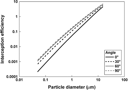
FIG. 6 Single-fiber interception efficiency versus particle diameter for several orientation angles. In all cases, aspect ratio is 6, solidity is 0.016, and the cross-sectional area is equivalent to that of a circular fiber with a 3 μ m diameter, about 7.07 μ m2.
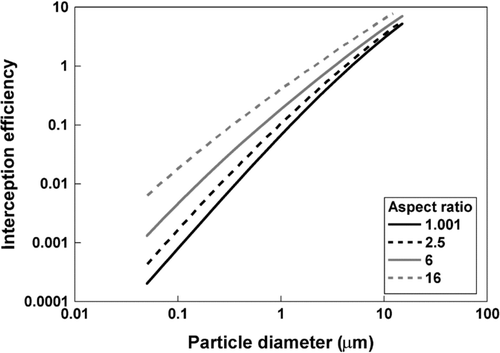
FIG. 7 Single-fiber interception efficiency versus particle diameter for several aspect ratios. In all cases, orientation angle is 90°, solidity is 0.016, and the cross-sectional area is equivalent to that of a circular fiber with a 3 μ m diameter, about 7.07 μ m2.

FIG. 7 Single-fiber interception efficiency versus particle diameter for several aspect ratios. In all cases, orientation angle is 90°, solidity is 0.016, and the cross-sectional area is equivalent to that of a circular fiber with a 3 μ m diameter, about 7.07 μ m2.

FIG. 8 Single-fiber interception efficiency versus particle diameter for several aspect ratios. In all cases, orientation angle is 0°, solidity is 0.016, and the cross sectional area is equivalent to that of a circular fiber with a 3 μ m diameter, about 7.07 μ m2.
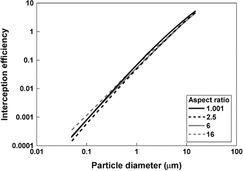
FIG. 8 Single-fiber interception efficiency versus particle diameter for several aspect ratios. In all cases, orientation angle is 0°, solidity is 0.016, and the cross sectional area is equivalent to that of a circular fiber with a 3 μ m diameter, about 7.07 μ m2.

FIG. 9 Single-fiber interception efficiency versus particle diameter for several values of solidity. In all cases, aspect ratio is 6, orientation angle is 90°, and the cross-sectional area is equivalent to that of a circular fiber with a 3 μ m diameter, about 7.07 μ m2.
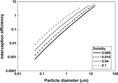
FIG. 9 Single-fiber interception efficiency versus particle diameter for several values of solidity. In all cases, aspect ratio is 6, orientation angle is 90°, and the cross-sectional area is equivalent to that of a circular fiber with a 3 μ m diameter, about 7.07 μ m2.

FIG. 10 Limiting streamlines for particles 1, 3, and 9 μ m in diameter plotted for conditions corresponding to . Orientation angles are (a) 0°, (b) 30°, (c) 60°, and (d) 90°. In all cases, aspect ratio is 6, solidity is 0.016, and the cross-sectional area is equivalent to that of a circular fiber with a 3 μ m diameter. The particles associated with each streamline are shown at the position at which they just touch the elliptical fiber.
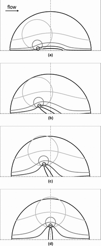
FIG. 10 Limiting streamlines for particles 1, 3, and 9 μ m in diameter plotted for conditions corresponding to Figure 6. Orientation angles are (a) 0°, (b) 30°, (c) 60°, and (d) 90°. In all cases, aspect ratio is 6, solidity is 0.016, and the cross-sectional area is equivalent to that of a circular fiber with a 3 μ m diameter. The particles associated with each streamline are shown at the position at which they just touch the elliptical fiber.
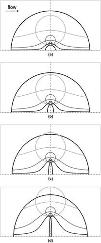
FIG. 11 Limiting streamlines for particles 1, 3, and 9 μ m in diameter plotted for conditions corresponding to . Aspect ratios are (a) 1.001, (b) 2.5, (c) 6, and (d) 16. In all cases, orientation angle is 90°, solidity is 0.016, and the cross-sectional area is equivalent to that of a circular fiber with a 3 μ m diameter. The particles associated with each streamline are shown at the position at which they just touch the elliptical fiber.
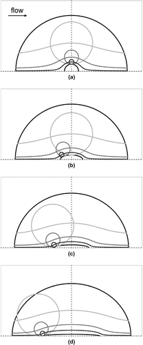
FIG. 11 Limiting streamlines for particles 1, 3, and 9 μ m in diameter plotted for conditions corresponding to Figure 7. Aspect ratios are (a) 1.001, (b) 2.5, (c) 6, and (d) 16. In all cases, orientation angle is 90°, solidity is 0.016, and the cross-sectional area is equivalent to that of a circular fiber with a 3 μ m diameter. The particles associated with each streamline are shown at the position at which they just touch the elliptical fiber.

FIG. 12 Limiting streamlines for particles 1, 3, and 9 μ m in diameter plotted for conditions corresponding to . Aspect ratios are (a) 1.001, (b) 2.5, (c) 6, and (d) 16. In all cases, orientation angle is 0°, solidity is 0.016, and the cross-sectional area is equivalent to that of a circular fiber with a 3 μ m diameter. The particles associated with each streamline are shown at the position at which they just touch the elliptical fiber.

FIG. 12 Limiting streamlines for particles 1, 3, and 9 μ m in diameter plotted for conditions corresponding to Figure 8. Aspect ratios are (a) 1.001, (b) 2.5, (c) 6, and (d) 16. In all cases, orientation angle is 0°, solidity is 0.016, and the cross-sectional area is equivalent to that of a circular fiber with a 3 μ m diameter. The particles associated with each streamline are shown at the position at which they just touch the elliptical fiber.

FIG. 13 Limiting streamlines for particles 1, 3, and 9 μ m in diameter plotted for conditions corresponding to . Solidity values are (a) 0.006, (b) 0.016, (c) 0.04, and (d) 0.1. In all cases, aspect ratio is 6, orientation angle is 90°, and the cross-sectional area is equivalent to that of a circular fiber with a 3 μ m diameter. The particles associated with each streamline are shown at the position at which they just touch the elliptical fiber. Particles 9 μ m in diameter are not presented in (c) and (d) because no limiting streamline passed through the solution domain.
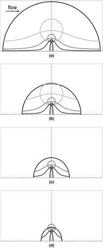
FIG. 13 Limiting streamlines for particles 1, 3, and 9 μ m in diameter plotted for conditions corresponding to Figure 9. Solidity values are (a) 0.006, (b) 0.016, (c) 0.04, and (d) 0.1. In all cases, aspect ratio is 6, orientation angle is 90°, and the cross-sectional area is equivalent to that of a circular fiber with a 3 μ m diameter. The particles associated with each streamline are shown at the position at which they just touch the elliptical fiber. Particles 9 μ m in diameter are not presented in (c) and (d) because no limiting streamline passed through the solution domain.

Reprints and Corporate Permissions

Please note: Selecting permissions does not provide access to the full text of the article, please see our help page How do I view content?

To request a reprint or corporate permissions for this article, please click on the relevant link below:

Academic Permissions

Please note: Selecting permissions does not provide access to the full text of the article, please see our help page How do I view content?

Obtain permissions instantly via Rightslink by clicking on the button below:

If you are unable to obtain permissions via Rightslink, please complete and submit this Permissions form. For more information, please visit our Permissions help page.