1,797
Views
73
CrossRef citations to date
0
Altmetric
Original Articles

An Eddy-Covariance System for the Measurement of Surface/Atmosphere Exchange Fluxes of Submicron Aerosol Chemical Species—First Application Above an Urban Area

, , , , , & show all
Pages 636-657 | Received 19 Nov 2007, Accepted 23 May 2008, Published online: 10 Jul 2008

Figures & data

FIG. 11 Averaged size-spectra of ammonium, nitrate, sulfate and organic aerosol (divided into HOA and OOA), in relation to the transmission function of CitationJayne et al. (2000). Towards the small size end, the size distribution of ammonium and OOA-I are affected by the contribution of O+ and CO2 + ions (from gas-phase O2 and CO2 molecules respectively behaving like small particles for the PToF measurement).
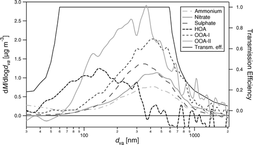
FIG. 11 Averaged size-spectra of ammonium, nitrate, sulfate and organic aerosol (divided into HOA and OOA), in relation to the transmission function of CitationJayne et al. (2000). Towards the small size end, the size distribution of ammonium and OOA-I are affected by the contribution of O+ and CO2 + ions (from gas-phase O2 and CO2 molecules respectively behaving like small particles for the PToF measurement).

FIG. 1 Raw measurement signal at 16.7 Hz comparing blocked to open beam (switched every 5 s), demonstrating the excellent signal/noise ratio of the Q-AMS instrument when sampling selected ions.
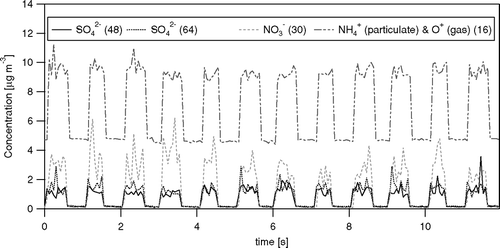
FIG. 1 Raw measurement signal at 16.7 Hz comparing blocked to open beam (switched every 5 s), demonstrating the excellent signal/noise ratio of the Q-AMS instrument when sampling selected ions.

FIG. 2 Signal from the selective ion monitoring as implemented in the JMS mode (conceptual schematic). For each selected m/z, the instrument scans the peak and the settles on the anticipated peak position.
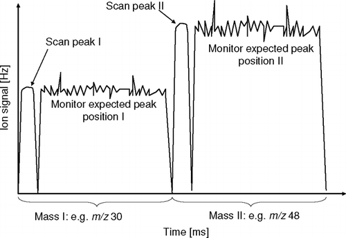
FIG. 2 Signal from the selective ion monitoring as implemented in the JMS mode (conceptual schematic). For each selected m/z, the instrument scans the peak and the settles on the anticipated peak position.

FIG. 3 Example peak shapes obtained during the JMS measurement cycle, averaged over 1 min. The symbols indicate the concentration derived during t meas, prior to subtraction of the DC signal level (derived from m/z = 9).
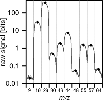
FIG. 3 Example peak shapes obtained during the JMS measurement cycle, averaged over 1 min. The symbols indicate the concentration derived during t meas, prior to subtraction of the DC signal level (derived from m/z = 9).

FIG. 4 Dependence of (a) averaging time and (b) duty cycle per m/z on sampling frequency (f), (c) effective overall efficiency and number of selected m/z (N m/z). The marker (•) illustrates the conditions as used during this study (10 m/z at 10 Hz).
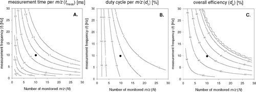
FIG. 4 Dependence of (a) averaging time and (b) duty cycle per m/z on sampling frequency (f), (c) effective overall efficiency and number of selected m/z (N m/z). The marker (•) illustrates the conditions as used during this study (10 m/z at 10 Hz).

FIG. 5 Example time series of the vertical wind components (w) and the NO3 concentration derived from m/z 30 for 16 June 2003, 12:30 PM. Shown are the raw 10 Hz data, and also a 1 s running mean for the concentration data (black line on the bottom panel).
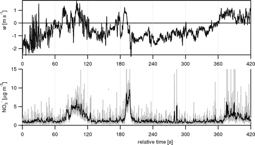
FIG. 5 Example time series of the vertical wind components (w) and the NO3 − concentration derived from m/z 30 for 16 June 2003, 12:30 PM. Shown are the raw 10 Hz data, and also a 1 s running mean for the concentration data (black line on the bottom panel).

FIG. 10 Comparison of (a) fitted relative mass spectra of HOA, OOA-I and OOA-II with (b) reference spectra representing SOA from humulene + O3 reaction, fully oxidised aerosol from a remote measurement site and diesel exhaust aerosol (FPEAK = −0.2).
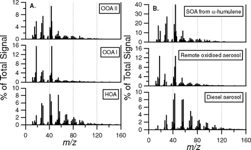
FIG. 10 Comparison of (a) fitted relative mass spectra of HOA, OOA-I and OOA-II with (b) reference spectra representing SOA from humulene + O3 reaction, fully oxidised aerosol from a remote measurement site and diesel exhaust aerosol (FPEAK = −0.2).

TABLE 1 Typical m/z chosen for the eddy-covariance JMS mode

FIG. 6 Aerial photograph of the area around the Williams Village measurement site. The white circle at the center of the figure marks the position of the measurement tower.
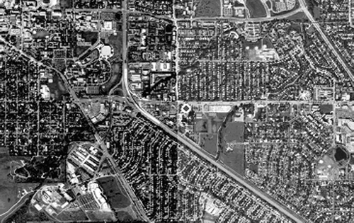
FIG. 6 Aerial photograph of the area around the Williams Village measurement site. The white circle at the center of the figure marks the position of the measurement tower.

FIG. 7 Overall MS spectrum of the measurement period, indicating the m/z monitored for fluxes. The numbers in the legend reflect the average concentrations in μg m−3. Please note the logarithmic scale.
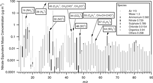
FIG. 7 Overall MS spectrum of the measurement period, indicating the m/z monitored for fluxes. The numbers in the legend reflect the average concentrations in μg m−3. Please note the logarithmic scale.

FIG. 8 Time-series of the 1 h average concentrations of non-refractory ammonium, nitrate, sulfate and total organics in NR-PM1 aerosol measured during the campaign in relation to meteorological variables (RH and precipitation are taken from the Foothills weather station, http://www.atd.ucar.edu/weather/weather_fl/station.html, operated by NCAR/ATD).
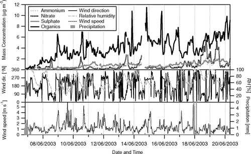
FIG. 8 Time-series of the 1 h average concentrations of non-refractory ammonium, nitrate, sulfate and total organics in NR-PM1 aerosol measured during the campaign in relation to meteorological variables (RH and precipitation are taken from the Foothills weather station, http://www.atd.ucar.edu/weather/weather_fl/station.html, operated by NCAR/ATD).

FIG. 9 Breakdown of hourly total organic aerosol loading in HOA, OOA-I and OOA-II using a three-component solution from PMF (FPEAK = −0.2).
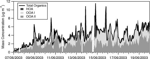
FIG. 9 Breakdown of hourly total organic aerosol loading in HOA, OOA-I and OOA-II using a three-component solution from PMF (FPEAK = −0.2).

TABLE 2 Summary of the average split of the monitored m/z representing organic aerosol into hydrocarbon like organic aerosol (HOA) and two classes of oxygenated organic aerosol (OOA) as calculated with PMF using different FPEAK values. Also shown is the resulting average concentration of the three different organic aerosol classes and their relative contribution to the total organic aerosol mass (OM), as well as the averaging fluxes derived from the different PMF solutions

FIG. 12 Comparison of (a) concentrations, (b) fluxes and (c) deposition velocities of SO4 2− derived from two different fragments, i.e., at m/z 48 (SO+) and m/z 64 (SO2 +). For fluxes and Vd, only data with SO4 2− concentrations > 1 μg m−3 are included. Linear regression lines are shown together with 95% confidence intervals.
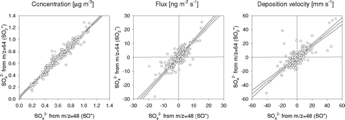
FIG. 12 Comparison of (a) concentrations, (b) fluxes and (c) deposition velocities of SO4 2− derived from two different fragments, i.e., at m/z 48 (SO+) and m/z 64 (SO2 +). For fluxes and Vd, only data with SO4 2− concentrations > 1 μg m−3 are included. Linear regression lines are shown together with 95% confidence intervals.

FIG. 14 Example time series of meteorological parameters, concentrations and fluxes observed over a 4 day period. Fluxes of aerosol components (FAMS) are presented as 3 h running means.
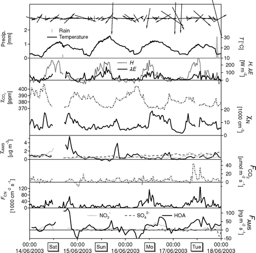
FIG. 14 Example time series of meteorological parameters, concentrations and fluxes observed over a 4 day period. Fluxes of aerosol components (FAMS) are presented as 3 h running means.

FIG. 16 Averaged diurnal cycles of chemically resolved particle concentrations and fluxes (FPEAK = −0.02).
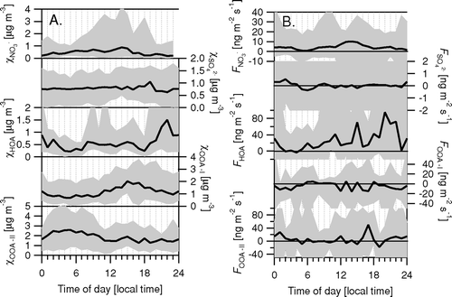
FIG. 16 Averaged diurnal cycles of chemically resolved particle concentrations and fluxes (FPEAK = −0.02).

FIG. 13 Normalised co-spectral density functions of the fluxes of sensible heat, momentum, nitrate (from m/z 46) and HOA (from m/z 57) for an example period (17 June 2003; 16:40), compared with the slope of f −4/3 expected in the inertial subrange. Empty symbols indicate negative contributions which were negated for plotting on the logarithmic scale.
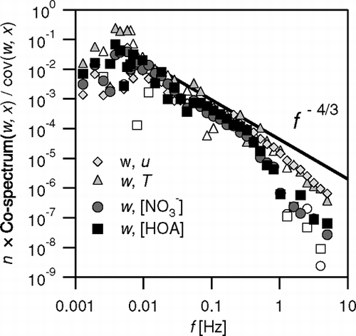
FIG. 13 Normalised co-spectral density functions of the fluxes of sensible heat, momentum, nitrate (from m/z 46) and HOA (from m/z 57) for an example period (17 June 2003; 16:40), compared with the slope of f −4/3 expected in the inertial subrange. Empty symbols indicate negative contributions which were negated for plotting on the logarithmic scale.

TABLE 3 Detection limits of the flux measurements (based on 30-minute averaging), compared with average fluxes measured during the campaign

FIG. 15 (a) Averaged diurnal cycles of temperature (T), water pressure (e) and concentrations of CO2CO2) and small particles (χCN). (b) Associated fluxes of sensible heat (H), latent heat (λE), CO2 (F CO2) and small particles (FCN). Shown are medians (bold lines), together with range between 5th and 95th percentiles.
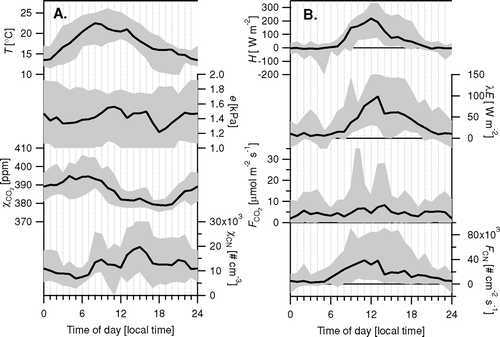
FIG. 15 (a) Averaged diurnal cycles of temperature (T), water pressure (e) and concentrations of CO2 (χCO2) and small particles (χCN). (b) Associated fluxes of sensible heat (H), latent heat (λE), CO2 (F CO2) and small particles (FCN). Shown are medians (bold lines), together with range between 5th and 95th percentiles.

FIG. 17 Correlation between the fluxes and deposition velocities derived from different m/z representing different components of the organic aerosol. Regression results: V d(55) = 0.57 V d(57)−4.25 mm s−1 (R2 = 0.85, N = 270); V d(44) = 0.083 V d(57) + 1.31 mm s−1 (R2 = 0.44, N = 270); V d(43) = 0.39 V d(57) − 0.55 mm s−1 (R2 = 0.85, N = 270); F OOA-I = −0.13 F HOA− 3.16 ng m−2 s−1 (R2 = 0.39, N = 270).
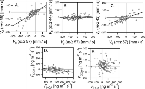
FIG. 17 Correlation between the fluxes and deposition velocities derived from different m/z representing different components of the organic aerosol. Regression results: V d(55) = 0.57 V d(57)−4.25 mm s−1 (R2 = 0.85, N = 270); V d(44) = 0.083 V d(57) + 1.31 mm s−1 (R2 = 0.44, N = 270); V d(43) = 0.39 V d(57) − 0.55 mm s−1 (R2 = 0.85, N = 270); F OOA-I = −0.13 F HOA− 3.16 ng m−2 s−1 (R2 = 0.39, N = 270).

FIG. 18 Values of the deposition velocities of SO4 2−, classified into bands of u* of width 0.1 m s−1. Each point constitutes an average of 6 to 64 data points.
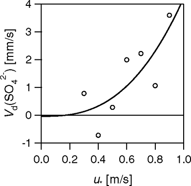
FIG. 18 Values of the deposition velocities of SO4 2−, classified into bands of u* of width 0.1 m s−1. Each point constitutes an average of 6 to 64 data points.

Reprints and Corporate Permissions

Please note: Selecting permissions does not provide access to the full text of the article, please see our help page How do I view content?

To request a reprint or corporate permissions for this article, please click on the relevant link below:

Academic Permissions

Please note: Selecting permissions does not provide access to the full text of the article, please see our help page How do I view content?

Obtain permissions instantly via Rightslink by clicking on the button below:

If you are unable to obtain permissions via Rightslink, please complete and submit this Permissions form. For more information, please visit our Permissions help page.