907
Views
8
CrossRef citations to date
0
Altmetric
Original Articles

Deposition of SiO2 Nanoparticles Produced in a Turbulent H2/Om2 Flame

, , , &
Pages 873-883 | Received 28 Feb 2008, Accepted 17 Jul 2008, Published online: 26 Sep 2008

Figures & data

FIG. 1 (a) Experimental set-up and (b) flame configurations (flames 1a, 2, and 3 from left to right).
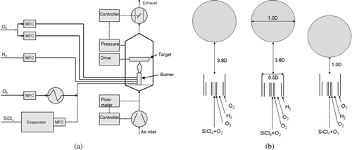
FIG. 1 (a) Experimental set-up and (b) flame configurations (flames 1a, 2, and 3 from left to right).

TABLE 1 Gas inlet velocities in m/s for the different flames

FIG. 3 Radial temperature profiles for different distances from the exit of the burner for flame 1a. Measured values are from CitationMüller et al. (2003) and calculation from .
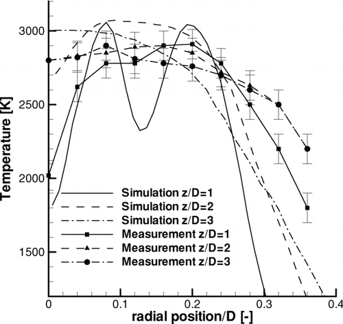
FIG. 3 Radial temperature profiles for different distances from the exit of the burner for flame 1a. Measured values are from CitationMüller et al. (2003) and calculation from Figure 5.

FIG. 2 Planar (a) and perpendicular (b) plots of calculated temperatures for flames 1a, 2, and 3 from left to right.
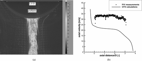
FIG. 2 Planar (a) and perpendicular (b) plots of calculated temperatures for flames 1a, 2, and 3 from left to right.

TABLE 2 Comparison of measured and predicted deposition efficiencies

FIG. 4 Planar (a) and perpendicular (b) plots of calculated streamwise velocities for flames 1a, 2, and 3 from left to right.
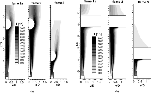
FIG. 4 Planar (a) and perpendicular (b) plots of calculated streamwise velocities for flames 1a, 2, and 3 from left to right.

FIG. 5 (a) Instantaneous image of the particle-laden flow with additional seeding and processed velocity vectors for flame 1a. (b) Measured and calculated streamwise mean velocity on the centre line as a function of streamwise position.
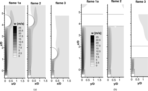
FIG. 5 (a) Instantaneous image of the particle-laden flow with additional seeding and processed velocity vectors for flame 1a. (b) Measured and calculated streamwise mean velocity on the centre line as a function of streamwise position.

FIG. 6 Planar plots of calculated streamwise velocity fluctuations for flames 1a, 2, and 3 from left to right.
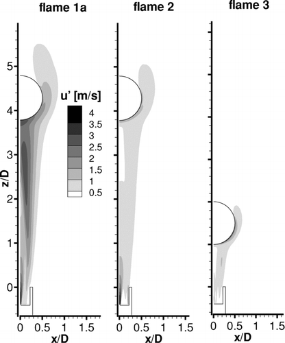
FIG. 6 Planar plots of calculated streamwise velocity fluctuations for flames 1a, 2, and 3 from left to right.

FIG. 7 Particle deposition locations on the cylinder for flames 1a, 2, and 3 from left to right.

FIG. 7 Particle deposition locations on the cylinder for flames 1a, 2, and 3 from left to right.

FIG. 8 Particle concentration on the central plane perpendicular to the cylinder for flame 1a (left), with thermophoretic force (middle), and laminar tracking (right).
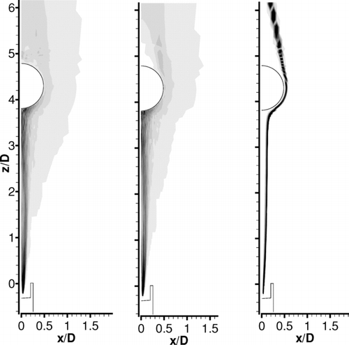
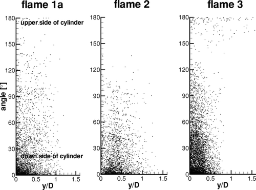
FIG. 8 Particle concentration on the central plane perpendicular to the cylinder for flame 1a (left), with thermophoretic force (middle), and laminar tracking (right).

Reprints and Corporate Permissions

Please note: Selecting permissions does not provide access to the full text of the article, please see our help page How do I view content?

To request a reprint or corporate permissions for this article, please click on the relevant link below:

Academic Permissions

Please note: Selecting permissions does not provide access to the full text of the article, please see our help page How do I view content?

Obtain permissions instantly via Rightslink by clicking on the button below:

If you are unable to obtain permissions via Rightslink, please complete and submit this Permissions form. For more information, please visit our Permissions help page.