Figures & data
FIG. 1 Schematic of the domains where the temperature and vapor concentration inside the UCPC are simulated.

FIG. 2 The frequency distribution of the 50% activation sizes (D p50) of 863 organic compounds (CitationYaws 1999). These results apply to all compounds from that compilation that have melting and boiling points below 20°C and 60°C, respectively.
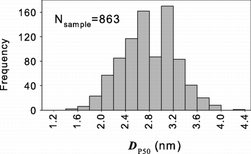
FIG. 3 The calculated 50% activation size, D p50, versus the surface tension evaluated at the temperature equal to the average of the saturator and condenser temperatures.
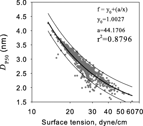
FIG. 4 (a) The calculated saturation ratio (b) the calculated 50% activation size, D p50, versus the saturation vapor pressure where the saturation ratio is the highest along the axis of the condenser.
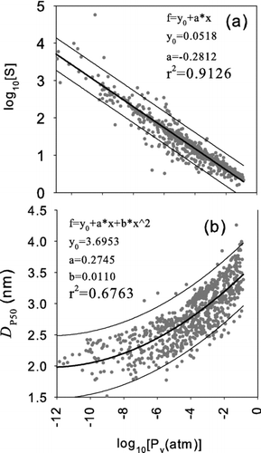
TABLE 1 Physical/chemical properties of the potential working fluids and parameters describing the performance of UCPC
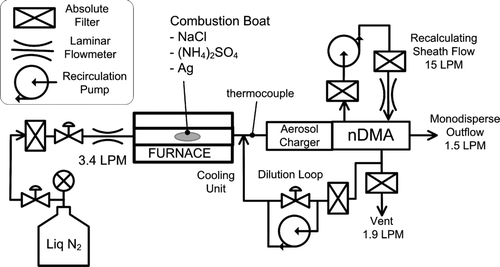
FIG. 8 Experimental setup for evaluating the activation efficiency of the Ultrafine CPC that uses various working fluids.
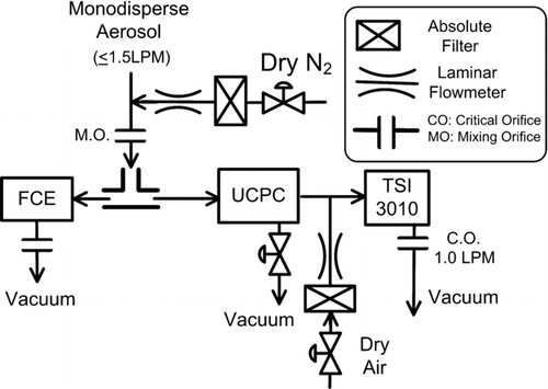
FIG. 9 Flow schematic of the ultrafine condensation particle counter, UCPC, and downstream TSI 3010 CPC.
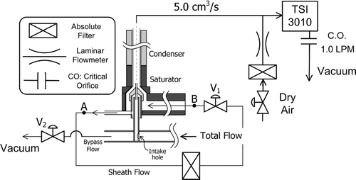
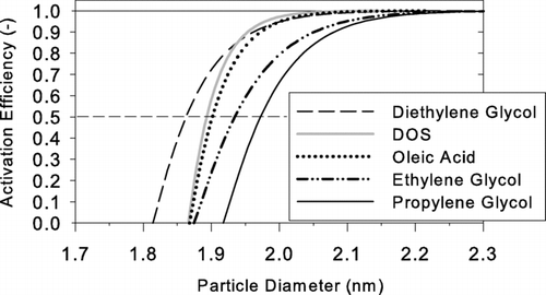
TABLE 2 The 50% cutoff size of activation curve for the working fluids investigated
FIG. 10 Measured activation efficiencies η of positively (left) and negatively charged (right) particles using diethylene glycol as working fluid and test aerosols generated from (a) silver, (b) ammonium sulfate, and (c) sodium chloride.
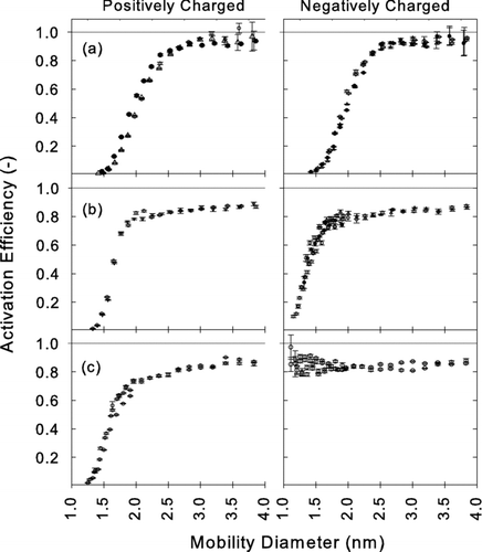
FIG. 11 Measured activation efficiencies η of positively charged (left) and negatively charged (right) particles using oleic acid as working fluid and test aerosols generated from (a) silver (b) ammonium sulfate and (c) sodium chloride.
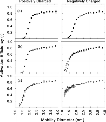
FIG. 12 Activation efficiencies η of ethylene glycol as a function of electrical mobility. The data were obtained by using test aerosols generated from sodium chloride. Mobility distributions of positive and negative ions generated from the aerosol charger are superimposed to illustrate the overlapping size range between ions and particles.
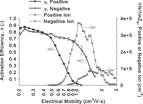
FIG. 13 The activation efficiencies versus time for detecting 2.3 nm (a) positively charged silver particles using ethylene glycol and (b) negatively charged silver particles using propylene glycol as working fluid.
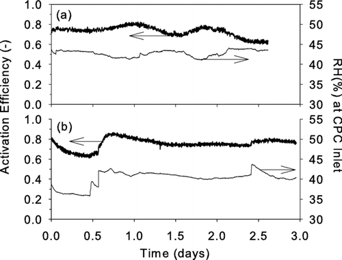
FIG. A1 Schematic of an approach for achieving nanoparticle activation and growth within a single laminar flow tube.

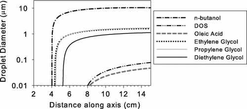
FIG. A2 The simulated droplet growth within growth activator and booster using the setup shown in as model input. The growth curve of n-butanol already shown in is also given as a reference.
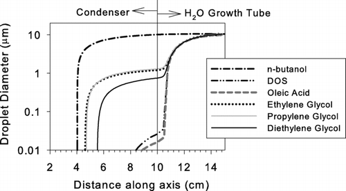
FIG. B1 Detailed schematics of the experimental setup for evaluating the activation efficiency of the Ultrafine CPC using (a) Nano-DMA as mobility classifier and the (b) UCPC and FCE as detectors
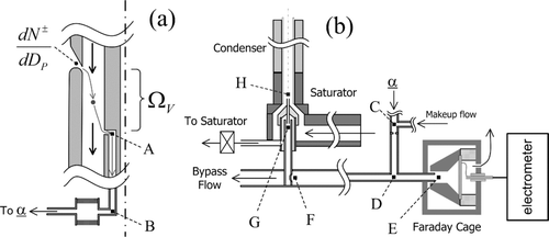
TABLE B1 Description of theoretically accounted diffusion losses through transport within the experimental setup
FIG. B2 Comparison of particle size distribution dN/dln D p of negatively charged particles at Nano-DMA inlet slit calculated by formal inversion (Equation [B1]) and by monodisperse approximation (Equation [B3]).
![FIG. B2 Comparison of particle size distribution dN/dln D p of negatively charged particles at Nano-DMA inlet slit calculated by formal inversion (Equation [B1]) and by monodisperse approximation (Equation [B3]).](/cms/asset/cf5322b7-0d0a-4344-8041-17e97f2eeb4a/uast_a_348987_o_f000b2g.gif)
FIG. B3 Concentration reaching Faraday cage electrometer (FCE) calculated from theoretical expression (Equation [B1]) using particles size distributions obtained by formal inversion and monodisperse approximation shown in . Experimentally measured concentrations are also given to show the goodness of fit.
![FIG. B3 Concentration reaching Faraday cage electrometer (FCE) calculated from theoretical expression (Equation [B1]) using particles size distributions obtained by formal inversion and monodisperse approximation shown in Figure B2. Experimentally measured concentrations are also given to show the goodness of fit.](/cms/asset/5e17129c-8b75-4e1e-bfc2-d088965f9e9a/uast_a_348987_o_f000b3g.gif)
FIG. B4 Comparison of activation efficiency η obtained by the monodisperse approximation (Equation [B6]), the formal inversion of Stolzenburg (Equations [B1] and [B2]), and the simplified approach introduced in this work (Equations [B4] and [B5]). The test particles are generated by evaporating the ammonium sulfate crystals.
![FIG. B4 Comparison of activation efficiency η obtained by the monodisperse approximation (Equation [B6]), the formal inversion of Stolzenburg (Equations [B1] and [B2]), and the simplified approach introduced in this work (Equations [B4] and [B5]). The test particles are generated by evaporating the ammonium sulfate crystals.](/cms/asset/fdab0d2a-8c48-4723-9ef0-dedfb62cfb4f/uast_a_348987_o_f000b4g.gif)
