783
Views
12
CrossRef citations to date
0
Altmetric
Original Articles

A Monte Carlo Model for Soil Particle Resuspension Including Saltation and Turbulent Fluctuations

&
Pages 161-173 | Received 18 Nov 2007, Accepted 08 Oct 2008, Published online: 14 Jan 2009

Figures & data

FIG. 1 Schematic of Monte Carlo simulation.

FIG. 1 Schematic of Monte Carlo simulation.

TABLE 1 Emission rates (kg m–2s−1) within the saltation layer except where noted. These data correspond to soils with different and, in some cases unknown, size distributions

FIG. 2 Mass flux rates within the saltation layer plotted against u3. Conditions were modeled to match Los Angeles and Allegheny County soil shown by diamonds and squares, respectively. For comparison purposes, flux estimates are shown from the models of CitationMarticorena and Bergametti (1995) and CitationGinoux et al. (2001). The fraction of soil available for resuspension was assumed to be 0.2 in both cases. The Ginoux et al. lines are virtually identical for the two case studies illustrated.
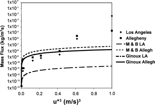
FIG. 2 Mass flux rates within the saltation layer plotted against u∗3. Conditions were modeled to match Los Angeles and Allegheny County soil shown by diamonds and squares, respectively. For comparison purposes, flux estimates are shown from the models of CitationMarticorena and Bergametti (1995) and CitationGinoux et al. (2001). The fraction of soil available for resuspension was assumed to be 0.2 in both cases. The Ginoux et al. lines are virtually identical for the two case studies illustrated.

TABLE 2 Simulated emission rates for particles within the saltation layer over a range of friction velocities. Units are m−2s−1

FIG. 3 Mass concentrations of suspended and saltating particles with friction velocities of 0.85 m s−1 and 1.0 m s−1. The simulation time was 3 seconds in all cases.
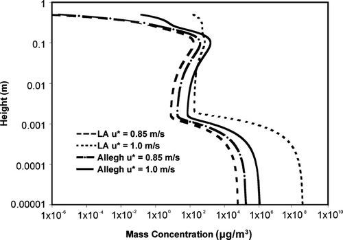
FIG. 3 Mass concentrations of suspended and saltating particles with friction velocities of 0.85 m s−1 and 1.0 m s−1. The simulation time was 3 seconds in all cases.

FIG. 4 The mass concentration of particles in full suspension for friction velocities of 0.50, 0.75, and 1.0 m s−1. Soil is characteristic of Los Angeles County. Particles in saltation are not shown.
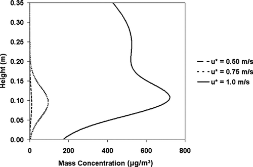
FIG. 4 The mass concentration of particles in full suspension for friction velocities of 0.50, 0.75, and 1.0 m s−1. Soil is characteristic of Los Angeles County. Particles in saltation are not shown.

FIG. 5 The mass concentration of particles in full suspension for friction velocities of 0.50, 0.75, and 1.0 m s−1. Soil is characteristic of Allegheny County. Particles in saltation are not shown.
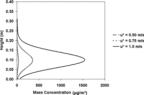
FIG. 5 The mass concentration of particles in full suspension for friction velocities of 0.50, 0.75, and 1.0 m s−1. Soil is characteristic of Allegheny County. Particles in saltation are not shown.

FIG. 6 The number concentration of suspended and saltating particles entrained in flows with u∗ = 0.85 m s−1 and 1.0 m s−1. The simulation time was 3 seconds in all cases.
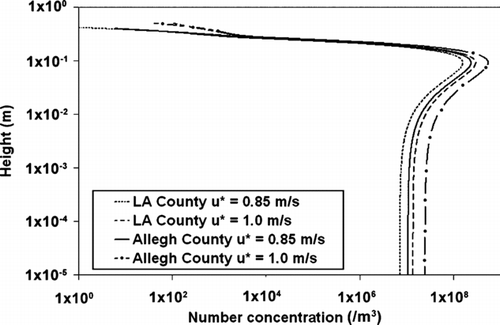
FIG. 6 The number concentration of suspended and saltating particles entrained in flows with u∗ = 0.85 m s−1 and 1.0 m s−1. The simulation time was 3 seconds in all cases.

FIG. 7 The number concentration of particles in full suspension for u∗ = 0.50, 0.75, and 1.0 m s−1. Soil is characteristic of Los Angeles County. Particles in saltation are not shown.
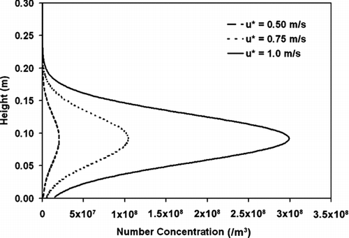
FIG. 7 The number concentration of particles in full suspension for u∗ = 0.50, 0.75, and 1.0 m s−1. Soil is characteristic of Los Angeles County. Particles in saltation are not shown.

FIG. 8 The number concentration of particles in full suspension for u∗ = 0.50, 0.75, and 1.0 m s−1. Soil is characteristic of Allegheny County. Particles in saltation are not shown.
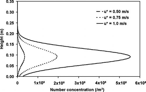
FIG. 8 The number concentration of particles in full suspension for u∗ = 0.50, 0.75, and 1.0 m s−1. Soil is characteristic of Allegheny County. Particles in saltation are not shown.

FIG. 9 The mean diameter calculated by both particle mass and particle number for Los Angeles and Allegheny Counties. Friction velocity is 0.75 m s−1.
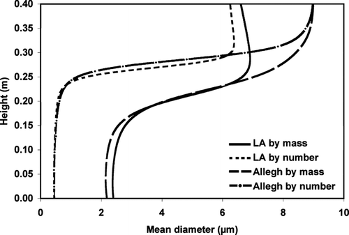
FIG. 9 The mean diameter calculated by both particle mass and particle number for Los Angeles and Allegheny Counties. Friction velocity is 0.75 m s−1.

TABLE 3 Regression coefficients and R 2 values for Equation (Equation9)

FIG. 10 Aerodynamic entrainment probabilities for a range of particle diameters and u∗ = 0.50, 0.75, and 1.0 m s−1.
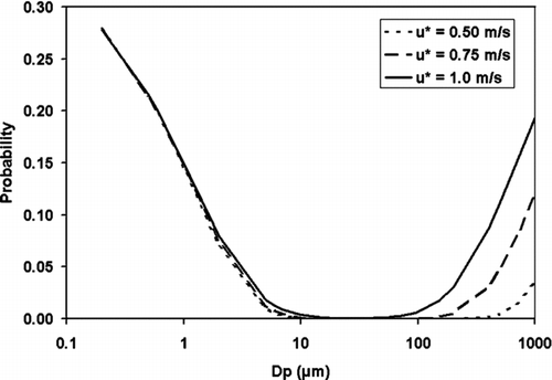
FIG. 10 Aerodynamic entrainment probabilities for a range of particle diameters and u∗ = 0.50, 0.75, and 1.0 m s−1.

FIG. 11 The mean horizontal wind profile with height during steady–state saltation is shown by the dotted line. A standard logarithmic profile is shown as a solid line for comparison. This is for u∗ = 0.75 m s−1, z o = 10−3 m, and a number flux of 3 × 10⁻⁹ m−2 s−1.
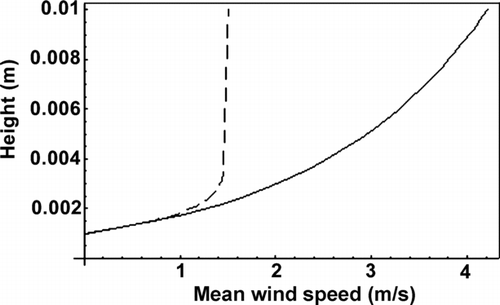
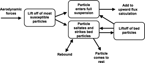
FIG. 11 The mean horizontal wind profile with height during steady–state saltation is shown by the dotted line. A standard logarithmic profile is shown as a solid line for comparison. This is for u∗ = 0.75 m s−1, z o = 10−3 m, and a number flux of 3 × 10⁻⁹ m−2 s−1.

Reprints and Corporate Permissions

Please note: Selecting permissions does not provide access to the full text of the article, please see our help page How do I view content?

To request a reprint or corporate permissions for this article, please click on the relevant link below:

Academic Permissions

Please note: Selecting permissions does not provide access to the full text of the article, please see our help page How do I view content?

Obtain permissions instantly via Rightslink by clicking on the button below:

If you are unable to obtain permissions via Rightslink, please complete and submit this Permissions form. For more information, please visit our Permissions help page.