1,197
Views
47
CrossRef citations to date
0
Altmetric
Original Articles

Quantitative Analysis of the Parameters Affecting In-Cabin to On-Roadway (I/O) Ultrafine Particle Concentration Ratios

&
Pages 400-410 | Received 09 Apr 2008, Accepted 18 Dec 2008, Published online: 26 Feb 2009

Figures & data

FIG. 1 Schematic representation of in-cabin particle dynamic processes. When the Fan is on and RC off, the outdoor air goes through a filter and the cracks on the doors into the cabin (solid line). When Fan and RC are both on, the air recirculated inside the vehicle is by passing through an in-cabin filter (dashed line).
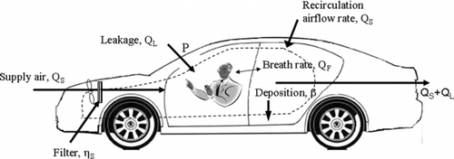
FIG. 1 Schematic representation of in-cabin particle dynamic processes. When the Fan is on and RC off, the outdoor air goes through a filter and the cracks on the doors into the cabin (solid line). When Fan and RC are both on, the air recirculated inside the vehicle is by passing through an in-cabin filter (dashed line).

TABLE 1 Equations used in the in-cabin mathematical model under different ventilation settings

FIG. 2 Differential pressure between the in-cabin and the ambient at various vehicle speeds for (a) a leaky (1997 model) and (b) a tight (2007 model) vehicle.
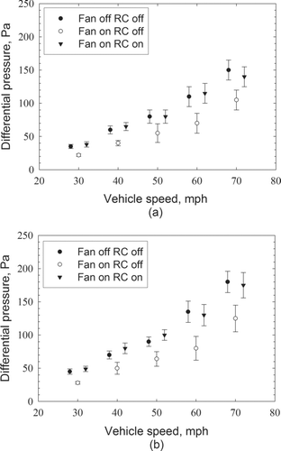
FIG. 2 Differential pressure between the in-cabin and the ambient at various vehicle speeds for (a) a leaky (1997 model) and (b) a tight (2007 model) vehicle.

FIG. 3 Size-segregated ranges of important input parameters for the in-cabin model (a) penetration factor (CitationLiu and Nazaroff 2003), (b) filtration efficiency (CitationQi et al. 2008), (c) deposition coefficient (CitationGong et al. 2009), and (d) respiratory deposition fraction (CitationHinds 1999).
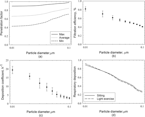
FIG. 3 Size-segregated ranges of important input parameters for the in-cabin model (a) penetration factor (CitationLiu and Nazaroff 2003), (b) filtration efficiency (CitationQi et al. 2008), (c) deposition coefficient (CitationGong et al. 2009), and (d) respiratory deposition fraction (CitationHinds 1999).

FIG. 4 Model results and measured data under (a) Fan off and RC off, (b) Fan on and RC off, and (c) Fan on and RC on conditions. Volume of the vehicle is 6 m3. The speed of vehicle is from 50 to 70 mph.
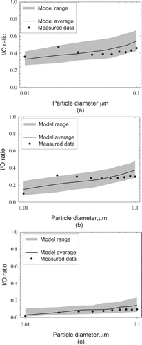
FIG. 4 Model results and measured data under (a) Fan off and RC off, (b) Fan on and RC off, and (c) Fan on and RC on conditions. Volume of the vehicle is 6 m3. The speed of vehicle is from 50 to 70 mph.

FIG. 5 Dynamic simulation of the in-cabin UFP concentrations compared with the measurement data (CitationZhu et al. 2007).
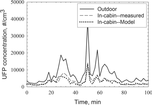
FIG. 5 Dynamic simulation of the in-cabin UFP concentrations compared with the measurement data (CitationZhu et al. 2007).

FIG. 6 Ranges of I/O ratios at different mechanical air flow rates for (a) 20 nm, (b) 50 nm, and (c) 80 nm particles. Airflow rate: max = 360 m3h−1, min = 0 m3 h−1. Drivers usually set the ventilation flow rate at a medium range, as “common situation” shown in the figure. All other parameters are set to average. Volume of vehicle is 6 m3. The speed of vehicle is 60 mph.
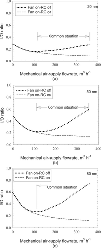
FIG. 6 Ranges of I/O ratios at different mechanical air flow rates for (a) 20 nm, (b) 50 nm, and (c) 80 nm particles. Airflow rate: max = 360 m3h−1, min = 0 m3 h−1. Drivers usually set the ventilation flow rate at a medium range, as “common situation” shown in the figure. All other parameters are set to average. Volume of vehicle is 6 m3. The speed of vehicle is 60 mph.

FIG. 7 Ranges of I/O ratios at different penetration factors for (a) 20 nm, (b) 50 nm, and (c) 80 nm particles. Penetration factors in the range of “previous studies” follow , and all other parameters are set to the average. Volume of vehicle is 6 m3. The speed of vehicle is 60 mph.
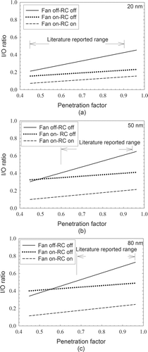
FIG. 7 Ranges of I/O ratios at different penetration factors for (a) 20 nm, (b) 50 nm, and (c) 80 nm particles. Penetration factors in the range of “previous studies” follow Figure 3a, and all other parameters are set to the average. Volume of vehicle is 6 m3. The speed of vehicle is 60 mph.
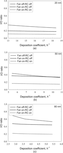
FIG. 8 Range of I/O ratios at different deposition coefficients for (a) 20 nm, (b) 50 nm, and (c) 80 nm particles. The range of deposition coefficients follow , and all other parameters are set to the average. Volume of vehicle is 6 m3. The speed of vehicle is 60 mph.

FIG. 8 Range of I/O ratios at different deposition coefficients for (a) 20 nm, (b) 50 nm, and (c) 80 nm particles. The range of deposition coefficients follow Figure 3c, and all other parameters are set to the average. Volume of vehicle is 6 m3. The speed of vehicle is 60 mph.

FIG. 9 Ranges of I/O ratios at different vehicle speeds for (a) 20 nm, (b) 50 nm, and (c) 80 nm particles. The range of vehicle speeds is from 20–70 mph. All other parameters are set to the average. Volume of vehicle is 6 m3.
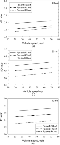
FIG. 9 Ranges of I/O ratios at different vehicle speeds for (a) 20 nm, (b) 50 nm, and (c) 80 nm particles. The range of vehicle speeds is from 20–70 mph. All other parameters are set to the average. Volume of vehicle is 6 m3.

FIG. 10 Time delays under different ventilation settings when outdoor UFP concentration changed to 2, 5, and 10 times what it was. The speed of vehicle is 60 mph.
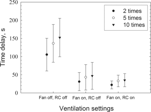
FIG. 10 Time delays under different ventilation settings when outdoor UFP concentration changed to 2, 5, and 10 times what it was. The speed of vehicle is 60 mph.

Reprints and Corporate Permissions

Please note: Selecting permissions does not provide access to the full text of the article, please see our help page How do I view content?

To request a reprint or corporate permissions for this article, please click on the relevant link below:

Academic Permissions

Please note: Selecting permissions does not provide access to the full text of the article, please see our help page How do I view content?

Obtain permissions instantly via Rightslink by clicking on the button below:

If you are unable to obtain permissions via Rightslink, please complete and submit this Permissions form. For more information, please visit our Permissions help page.