776
Views
7
CrossRef citations to date
0
Altmetric
Original Articles

The 1-by-3 Tandem Differential Mobility Analyzer for Measurement of the Irreversibility of the Hygroscopic Growth Factor

, &
Pages 641-652 | Received 09 Aug 2008, Accepted 29 Jan 2009, Published online: 08 Apr 2009

Figures & data

FIG. 1 Diagram of the 1-by-3 tandem differential mobility analyzer (1 × 3-TDMA) for measurement of the irreversibility of the hygroscopic growth factor. The principles of the 1 × 3-TDMA operation are described in the text. Legend: RH0, adjustment of aerosol relative humidity to a central value; RH, adjustment of aerosol relative humidity to RH0+ |δ|; RH−δ, adjustment of aerosol relative humidity to RH0−|δ|; DMA, differential mobility analyzer (all tuned to the same electric mobility); CPC, condensation particle counter.
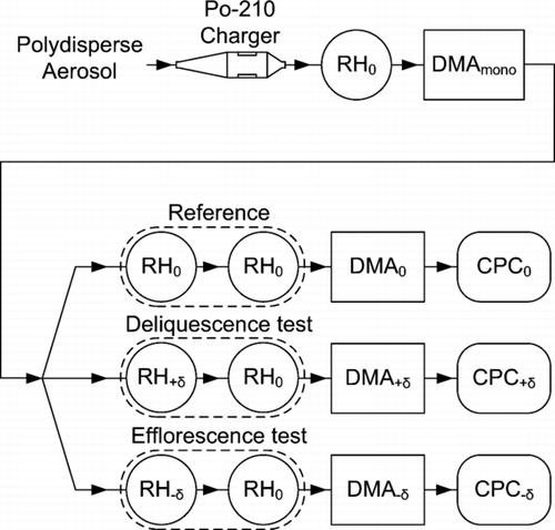
FIG. 1 Diagram of the 1-by-3 tandem differential mobility analyzer (1 × 3-TDMA) for measurement of the irreversibility of the hygroscopic growth factor. The principles of the 1 × 3-TDMA operation are described in the text. Legend: RH0, adjustment of aerosol relative humidity to a central value; RH+δ, adjustment of aerosol relative humidity to RH0+ |δ|; RH−δ, adjustment of aerosol relative humidity to RH0−|δ|; DMA, differential mobility analyzer (all tuned to the same electric mobility); CPC, condensation particle counter.

FIG. 2 (top) Theoretical hygroscopic growth curve of 100 nm sodium chloride particles modeled for a conventional HTDMA (CitationBiskos et al. 2006a). Left and right panels represent deliquescence and efflorescence scans for particles initialized in solid and aqueous particles, respectively. Arrows indicate the direction of the RH scan. (bottom) Theoretical 1 × 3-TDMA response (|δ|= 5), which is shown as the particle transmission ratio for the similar RH scans as the top row. The transmission ratio is defined as (left) the concentration count from CPC divided by that of CPC0 for the deliquescence test and (right) the concentration count from CPC−δ divided by that of CPC0 for the efflorescence test. For the deliquescence test, the transmission ratio drops below unity at RH0 values for which a perturbation of +|δ| yields an irreversible change in the growth factor of solid particles (i.e., DRH – |δ|< RH0< DRH). Efflorescence likewise induces an irreversible response in the growth factor for aqueous particles for a perturbation of -|δ| over the range ERH < RH0< ERH + |δ|.
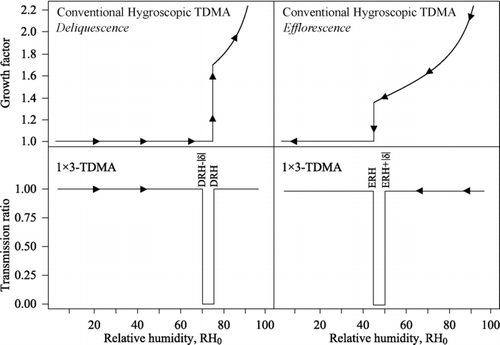
FIG. 2 (top) Theoretical hygroscopic growth curve of 100 nm sodium chloride particles modeled for a conventional HTDMA (CitationBiskos et al. 2006a). Left and right panels represent deliquescence and efflorescence scans for particles initialized in solid and aqueous particles, respectively. Arrows indicate the direction of the RH scan. (bottom) Theoretical 1 × 3-TDMA response (|δ|= 5), which is shown as the particle transmission ratio for the similar RH scans as the top row. The transmission ratio is defined as (left) the concentration count from CPC+δ divided by that of CPC0 for the deliquescence test and (right) the concentration count from CPC−δ divided by that of CPC0 for the efflorescence test. For the deliquescence test, the transmission ratio drops below unity at RH0 values for which a perturbation of +|δ| yields an irreversible change in the growth factor of solid particles (i.e., DRH – |δ|< RH0< DRH). Efflorescence likewise induces an irreversible response in the growth factor for aqueous particles for a perturbation of -|δ| over the range ERH < RH0< ERH + |δ|.

FIG. 3 Simulation showing the evolution of the number size distribution of sodium chloride particles inside the 1 × 3-TDMA for a deliquescence test. The three columns respectively show the distribution at RH0 prior to entering DMA mono (cf. ), after exiting DMA mono , and after the deliquescence test of RH0+ δ back to RH0 (δ=+5). The three rows successively show steps of RH0 from 67, to 72, to 77%. The black vertical bars show 0% transmission edges for 100-nm mobility diameter (one-charge equivalent). Distributions corresponding to aqueous particles are shown in red and those corresponding to solid particles are shown in blue.
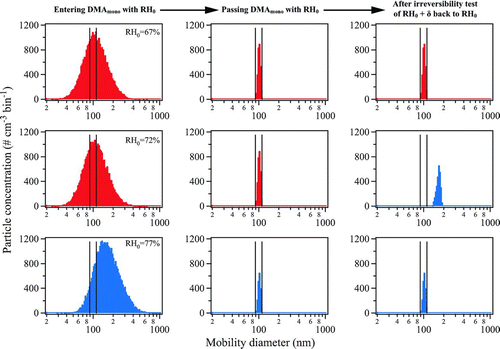
FIG. 3 Simulation showing the evolution of the number size distribution of sodium chloride particles inside the 1 × 3-TDMA for a deliquescence test. The three columns respectively show the distribution at RH0 prior to entering DMA mono (cf. Figure 1), after exiting DMA mono , and after the deliquescence test of RH0+ δ back to RH0 (δ=+5). The three rows successively show steps of RH0 from 67, to 72, to 77%. The black vertical bars show 0% transmission edges for 100-nm mobility diameter (one-charge equivalent). Distributions corresponding to aqueous particles are shown in red and those corresponding to solid particles are shown in blue.

FIG. 4 Simulation of the 1 × 3-TDMA response showing (A1) the number concentration of particles reaching CPC0 in red and CPC in blue when RH0 is scanned from low to high (i.e., “a deliquescence scan”), (B1) the concentration of particles reaching CPC0 in red and CPC−δ in blue when RH0 is scanned from high to low (i.e., “an efflorescence scan”), (A2) the ratio CPC:CPC0 for the deliquescence scan, and (B2) the ratio CPC−δ:CPC0 for the efflorescence scan. Conditions: a test aerosol of 50,000 aqueous NaCl particles and 50,000 solid NaCl particles for the 1 × 3-TDMA set at a 100-nm mobility diameter (one-charge equivalent) and δ= ±5%. The size distribution of the particles prior to DMA0 is the same as in . The difference in the minimum transmission ratios (i.e., different from 0.5) in panels A2 and B2 as well as the noise in the simulation are attributable to insufficient particle counting statistics (i.e., more than 100,000 particles are necessary in the simulation to get an ideal response).
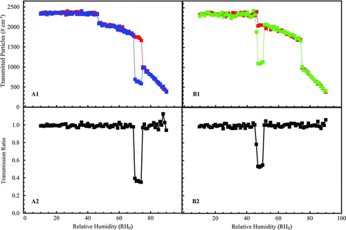
FIG. 4 Simulation of the 1 × 3-TDMA response showing (A1) the number concentration of particles reaching CPC0 in red and CPC+δ in blue when RH0 is scanned from low to high (i.e., “a deliquescence scan”), (B1) the concentration of particles reaching CPC0 in red and CPC−δ in blue when RH0 is scanned from high to low (i.e., “an efflorescence scan”), (A2) the ratio CPC+δ:CPC0 for the deliquescence scan, and (B2) the ratio CPC−δ:CPC0 for the efflorescence scan. Conditions: a test aerosol of 50,000 aqueous NaCl particles and 50,000 solid NaCl particles for the 1 × 3-TDMA set at a 100-nm mobility diameter (one-charge equivalent) and δ= ±5%. The size distribution of the particles prior to DMA0 is the same as in Figure 3. The difference in the minimum transmission ratios (i.e., different from 0.5) in panels A2 and B2 as well as the noise in the simulation are attributable to insufficient particle counting statistics (i.e., more than 100,000 particles are necessary in the simulation to get an ideal response).

FIG. 5 Diagnostics and data recorded for a test aerosol of externally mixed aqueous and solid particles of aqueous and solid NaCl particles (80:20 mixture) with the 1 × 3-TMDA set to 100-nm mobility diameter (one-charge equivalent) and δ= ±5%. The figure shows the reproducibility and the stability of measurements. (a) Diagnostics of the relative humidities RH, RH−δ, and RH0 in the test arms and the reference arm, the differences in RH between the test arms and the reference arm (i.e., δ), and the difference in the reference arm between the measured RH and its setpoint. (b) Data of the CPC measurements CPC0, CPC, and CPC−δ for the three test arms and the corresponding transmission ratios CPC:CPC0 and CPC−δ:CPC0. The labeled spikes i to iv are discussed in the text. For clarity, except for the final full upscan-downscan represented by the gray boxes, the upscan CPC−δ:CPC0 and the downscan CPC:CPC0 are omitted from the figure because these data are not included in the later analysis.

FIG. 5 Diagnostics and data recorded for a test aerosol of externally mixed aqueous and solid particles of aqueous and solid NaCl particles (80:20 mixture) with the 1 × 3-TMDA set to 100-nm mobility diameter (one-charge equivalent) and δ= ±5%. The figure shows the reproducibility and the stability of measurements. (a) Diagnostics of the relative humidities RH+δ, RH−δ, and RH0 in the test arms and the reference arm, the differences in RH between the test arms and the reference arm (i.e., δ), and the difference in the reference arm between the measured RH and its setpoint. (b) Data of the CPC measurements CPC0, CPC+δ, and CPC−δ for the three test arms and the corresponding transmission ratios CPC+δ:CPC0 and CPC−δ:CPC0. The labeled spikes i to iv are discussed in the text. For clarity, except for the final full upscan-downscan represented by the gray boxes, the upscan CPC−δ:CPC0 and the downscan CPC+δ:CPC0 are omitted from the figure because these data are not included in the later analysis.
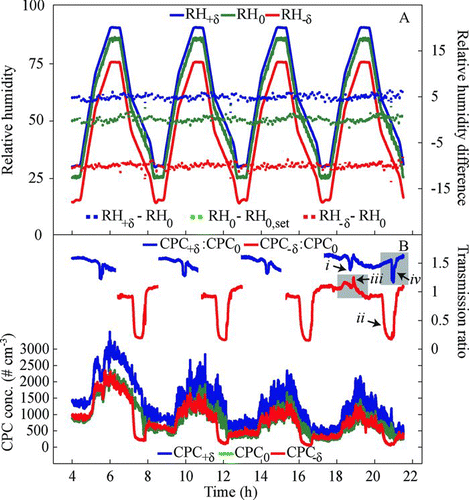
FIG. 6 1 × 3-TDMA response of CPC:CPC0 and CPC−δ:CPC0 to test aerosols of externally mixed aqueous and solid particles of (a) ammonium sulfate (50:50 mixture; δ= ±5%) and (b) sodium chloride (85:15 mixture; δ=+5% for the deliquescence test and δ= −10% for the efflorescence test). Only upscans are shown for deliquescence (blue) and only downscans for efflorescence (red). The selected mobility diameter is 100 nm (one-charge equivalent).
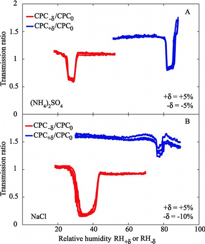
FIG. 6 1 × 3-TDMA response of CPC+δ:CPC0 and CPC−δ:CPC0 to test aerosols of externally mixed aqueous and solid particles of (a) ammonium sulfate (50:50 mixture; δ= ±5%) and (b) sodium chloride (85:15 mixture; δ=+5% for the deliquescence test and δ= −10% for the efflorescence test). Only upscans are shown for deliquescence (blue) and only downscans for efflorescence (red). The selected mobility diameter is 100 nm (one-charge equivalent).

FIG. 7 1 × 3-TDMA response of CPC:CPC0 and CPC−δ:CPC0 to test aerosols of (a) a 20:10:40:20 mix of AS(aq):AS(s):NaCl(aq):NaCl(s) externally mixed particles and with 1 × 3-TDMA set to δ= ±3% and (b) a 50:50 mix of low-RH (exposed to RH < 5%) and high-RH (exposed to RH > 95%) sea salt particles with 1 × 3-TDMA set to δ= ±5%. Other conditions and labeling are as for .
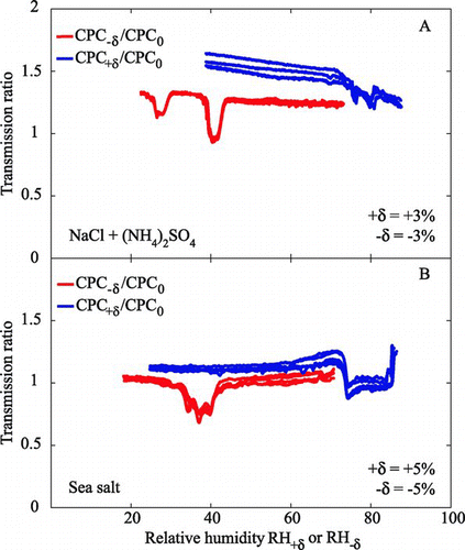
FIG. 7 1 × 3-TDMA response of CPC+δ:CPC0 and CPC−δ:CPC0 to test aerosols of (a) a 20:10:40:20 mix of AS(aq):AS(s):NaCl(aq):NaCl(s) externally mixed particles and with 1 × 3-TDMA set to δ= ±3% and (b) a 50:50 mix of low-RH (exposed to RH < 5%) and high-RH (exposed to RH > 95%) sea salt particles with 1 × 3-TDMA set to δ= ±5%. Other conditions and labeling are as for Figure 6.

TABLE 1 Transmission ratios for five subdomains of RH0 during efflorescence and deliquescence scans. The test aerosol before entering the 1 × 3-TDMA consists of a fraction faq of aqueous particles and a fraction fsol of solid particles

Supplemental material

UAST_A_382371_SUP_0001.zip

Download Zip (731.1 KB)

Reprints and Corporate Permissions

Please note: Selecting permissions does not provide access to the full text of the article, please see our help page How do I view content?

To request a reprint or corporate permissions for this article, please click on the relevant link below:

Academic Permissions

Please note: Selecting permissions does not provide access to the full text of the article, please see our help page How do I view content?

Obtain permissions instantly via Rightslink by clicking on the button below:

If you are unable to obtain permissions via Rightslink, please complete and submit this Permissions form. For more information, please visit our Permissions help page.