1,793
Views
70
CrossRef citations to date
0
Altmetric
Original Articles

Experimental Investigation on Continuous Filtration of Sub-Micron Aerosol by Filter Composed of Dual-Layers Including a Nanofiber Layer

, &
Pages 1174-1183 | Received 04 Mar 2009, Accepted 03 Aug 2009, Published online: 05 Oct 2009

Figures & data

TABLE 1 Properties of constituent filter layers

FIG. 1 Stacking of constituent filter layers within the dual-layer filters E, F, and G.

FIG. 1 Stacking of constituent filter layers within the dual-layer filters E, F, and G.

FIG. 2 Schematic of experimental set-up for testing of fractional efficiency (scheme 1) and loading up test filter (scheme 2).
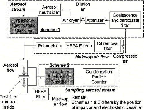
FIG. 2 Schematic of experimental set-up for testing of fractional efficiency (scheme 1) and loading up test filter (scheme 2).

FIG. 3 Size distribution of aerosol stream loading up filters A, D, E, and F.

FIG. 3 Size distribution of aerosol stream loading up filters A, D, E, and F.

FIG. 4 Fractional efficiencies of clean filters A, B, C, D, and F.

FIG. 4 Fractional efficiencies of clean filters A, B, C, D, and F.

FIG. 5 Quality factors of clean filters A, B, C, D, and F.

FIG. 5 Quality factors of clean filters A, B, C, D, and F.

FIG. 6 Fractional efficiencies of (a) filter A, (b) filter B, (c) filter C, and (d) filter D under continuous loading.

FIG. 6 Fractional efficiencies of (a) filter A, (b) filter B, (c) filter C, and (d) filter D under continuous loading.

FIG. 7 Change of MPPS of filters A, B, C, and D under continuous loading.

FIG. 7 Change of MPPS of filters A, B, C, and D under continuous loading.

FIG. 8 Pressure drop elevation of (a) filters A, B, C, and (b) filter D under continuous loading.

FIG. 8 Pressure drop elevation of (a) filters A, B, C, and (b) filter D under continuous loading.

FIG. 9 Deposition profile of filters A, B, C, and D after collected 4 gm− 2 deposit.

FIG. 9 Deposition profile of filters A, B, C, and D after collected 4 gm− 2 deposit.

FIG. 10 Validating the semi-empirical model.

FIG. 10 Validating the semi-empirical model.

FIG. 11 Fractional efficiencies of (a) filter E and (b) filter F under continuous loading.

FIG. 11 Fractional efficiencies of (a) filter E and (b) filter F under continuous loading.

FIG. 12 Pressure drop across filters E, F, and G under continuous loading.

FIG. 12 Pressure drop across filters E, F, and G under continuous loading.

FIG. 13 Deposition profile of filters E and F after collected 5 gm− 2 deposit.

FIG. 13 Deposition profile of filters E and F after collected 5 gm− 2 deposit.

FIG. 14 Deposition profile of filter G after collected 5 gm− 2 deposit (N = 50).

FIG. 14 Deposition profile of filter G after collected 5 gm− 2 deposit (N = 50).

FIG. 15 Alternative loading and cleaning cycles of filter A.

FIG. 15 Alternative loading and cleaning cycles of filter A.

Reprints and Corporate Permissions

Please note: Selecting permissions does not provide access to the full text of the article, please see our help page How do I view content?

To request a reprint or corporate permissions for this article, please click on the relevant link below:

Academic Permissions

Please note: Selecting permissions does not provide access to the full text of the article, please see our help page How do I view content?

Obtain permissions instantly via Rightslink by clicking on the button below:

If you are unable to obtain permissions via Rightslink, please complete and submit this Permissions form. For more information, please visit our Permissions help page.