1,043
Views
3
CrossRef citations to date
0
Altmetric
Original Articles

Image Analysis and Computer Simulation of Nanoparticle Clustering in Combustion Systems

, , &
Pages 83-95 | Received 17 Jun 2009, Accepted 02 Oct 2009, Published online: 13 Jul 2010

Figures & data

TABLE 1 Methods used to validate and/or represent interactions between nanoparticle collisions

FIG. 1 Transmission electron micrograph image of flame-generated tin dioxide nanoparticle cluster.

FIG. 1 Transmission electron micrograph image of flame-generated tin dioxide nanoparticle cluster.

FIG. 2 Schematic of the combustion synthesis facility used to create the tin dioxide nanoparticles.

FIG. 2 Schematic of the combustion synthesis facility used to create the tin dioxide nanoparticles.

FIG. 3 Schematic representing the (a) Case 1 binding method (van der Waals interactions) and (b) Case 2 binding method (Coulomb forces). The gray particles are particles existing within the computational boundary, and the black particle is the new particle searching for a binding site. The gray particle circled in black is the randomly chosen particle for binding.

FIG. 3 Schematic representing the (a) Case 1 binding method (van der Waals interactions) and (b) Case 2 binding method (Coulomb forces). The gray particles are particles existing within the computational boundary, and the black particle is the new particle searching for a binding site. The gray particle circled in black is the randomly chosen particle for binding.

FIG. 4 Simulation results for a b as a function of P1 for cluster sizes N = 20, 40, 60, 80, and 100.
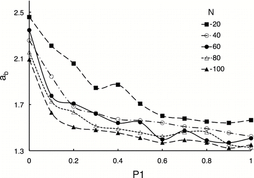
FIG. 4 Simulation results for a b as a function of P1 for cluster sizes N = 20, 40, 60, 80, and 100.

FIG. 5 Simulation results for notched box plots of the effect of P1 on aspect ratio a b for N = (a) 20, (b) 60, and (c) 100.
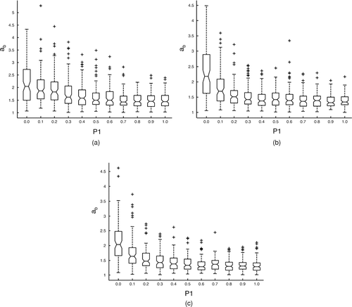
FIG. 5 Simulation results for notched box plots of the effect of P1 on aspect ratio a b for N = (a) 20, (b) 60, and (c) 100.

FIG. 6 Simulation results of the effect of P1 on average main chain length normalized by particle radius, L m /r, for cluster sizes N = 20, 40, 60, 80, and 100.
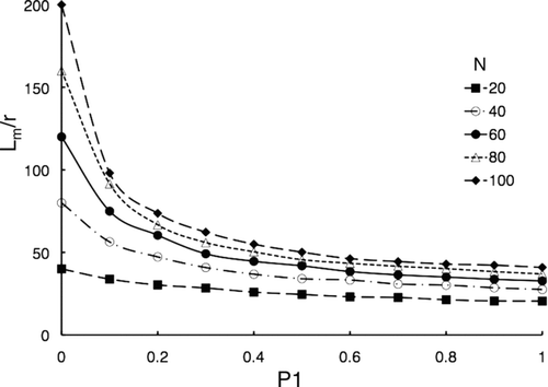
FIG. 6 Simulation results of the effect of P1 on average main chain length normalized by particle radius, L m /r, for cluster sizes N = 20, 40, 60, 80, and 100.

FIG. 7 Simulation results of the effect of P1 on normalized main chain length, L m /(Nr), for cluster sizes N = 20, 40, 60, 80, and 100.
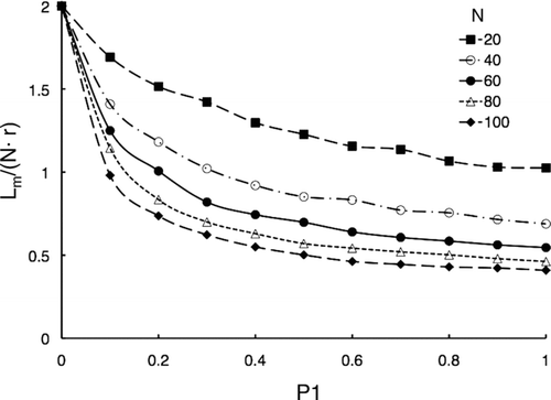
FIG. 7 Simulation results of the effect of P1 on normalized main chain length, L m /(Nr), for cluster sizes N = 20, 40, 60, 80, and 100.

FIG. 8 Simulation results for notched box plots of the effect of P1 on L m /r when N = (a) 20, (b) 60, and (c) 100.
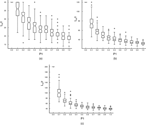
FIG. 8 Simulation results for notched box plots of the effect of P1 on L m /r when N = (a) 20, (b) 60, and (c) 100.

FIG. 9 Simulation results for the effects of P1 on average radius of gyration, R g /r, for cluster sizes N = 20, 40, 60, 80, and 100.
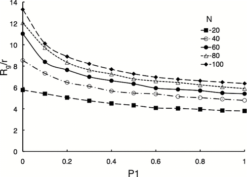
FIG. 9 Simulation results for the effects of P1 on average radius of gyration, R g /r, for cluster sizes N = 20, 40, 60, 80, and 100.

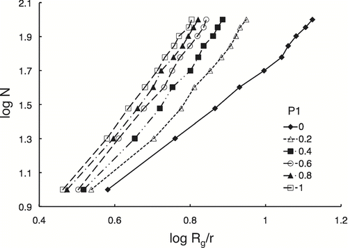
FIG. 10 Simulation results to evaluate the self-similarity of the predicted particle clusters.

FIG. 10 Simulation results to evaluate the self-similarity of the predicted particle clusters.

FIG. 11 Simulation results for fractal dimension D f and fractal pre-factor A as a function of P1 using 3D data and 2D projections of the 3D data.
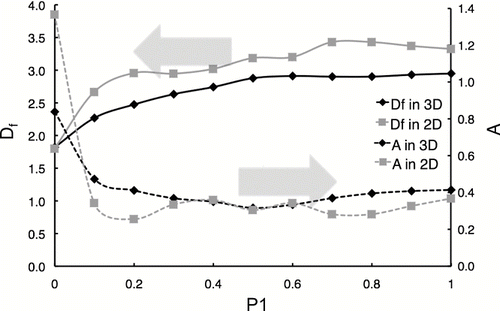
FIG. 11 Simulation results for fractal dimension D f and fractal pre-factor A as a function of P1 using 3D data and 2D projections of the 3D data.

FIG. 12 Simulation results of the effects of P1 on the ratio of L m in 2D to R g in 3D for cluster sizes N = 20, 40, 60, 80, and 100.
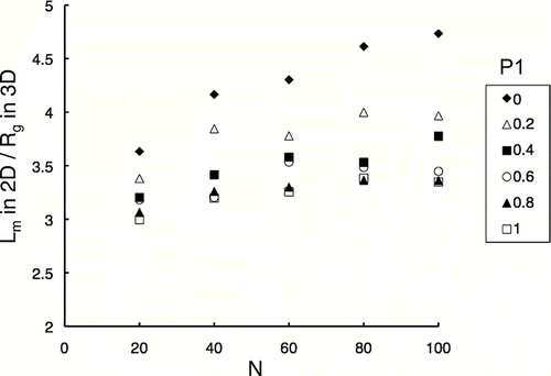
FIG. 12 Simulation results of the effects of P1 on the ratio of L m in 2D to R g in 3D for cluster sizes N = 20, 40, 60, 80, and 100.

FIG. 13 TEM images of agglomerate I at different tilt angles: (a) −55°, (b) 0°, and (c) +55°.

FIG. 13 TEM images of agglomerate I at different tilt angles: (a) −55°, (b) 0°, and (c) +55°.

FIG. 14 2D projections of 3D model of agglomerate I at different angles of orientation: (a) −55°, (b) 0°, (c) +55°, (d) +110°, and (e) 165°.

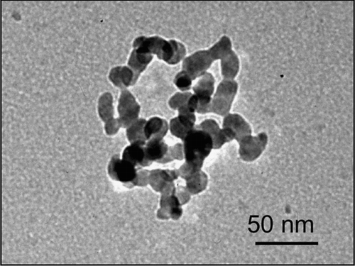
FIG. 14 2D projections of 3D model of agglomerate I at different angles of orientation: (a) −55°, (b) 0°, (c) +55°, (d) +110°, and (e) 165°.
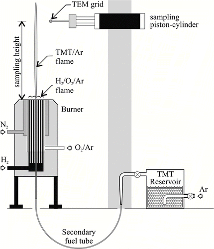
TABLE 2 Results of image analysis of SnO2 nanoparticle clusters.

Supplemental material

uast_a_439216_sup_11784433.zip

Download Zip (2.5 MB)

Reprints and Corporate Permissions

Please note: Selecting permissions does not provide access to the full text of the article, please see our help page How do I view content?

To request a reprint or corporate permissions for this article, please click on the relevant link below:

Academic Permissions

Please note: Selecting permissions does not provide access to the full text of the article, please see our help page How do I view content?

Obtain permissions instantly via Rightslink by clicking on the button below:

If you are unable to obtain permissions via Rightslink, please complete and submit this Permissions form. For more information, please visit our Permissions help page.