497
Views
7
CrossRef citations to date
0
Altmetric
Original Articles

Numerical Study of Thin-Walled Sampler Performance for Aerosols in Low Windspeed Environments

, &
Pages 152-160 | Received 25 May 2009, Accepted 03 Oct 2009, Published online: 13 Jul 2010

Figures & data

FIG. 1 Streamlines (a) and particle trajectories (b) for the aspiration into the tube.

FIG. 1 Streamlines (a) and particle trajectories (b) for the aspiration into the tube.

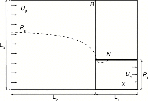
FIG. 2 The scheme of calculation domain in plane (X,R): dashed line is the limiting streamline.

FIG. 2 The scheme of calculation domain in plane (X,R): dashed line is the limiting streamline.

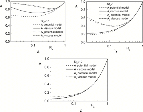
FIG. 3 The dependencies of aspiration efficiency on R a for various values of St.

FIG. 3 The dependencies of aspiration efficiency on R a for various values of St.

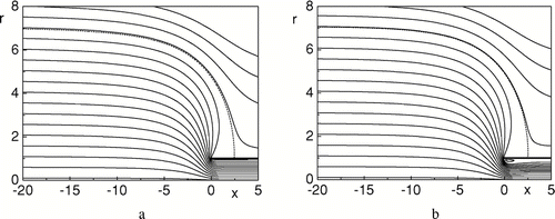
FIG. 4 Streamlines at R a = 0.02 for potential (a) and viscous (b) flow models.

FIG. 4 Streamlines at R a = 0.02 for potential (a) and viscous (b) flow models.

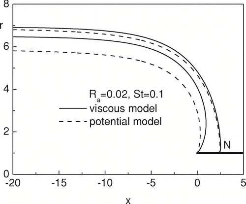
FIG. 5 Limiting particle trajectory at R a = 0.02 and St = 0.1.

FIG. 5 Limiting particle trajectory at R a = 0.02 and St = 0.1.

FIG. 6 The comparison of the dependencies A i (R a ) and A e (R a ) with experimental data from CitationGibson and Ogden (1977) and CitationDavies and Subari (1982).
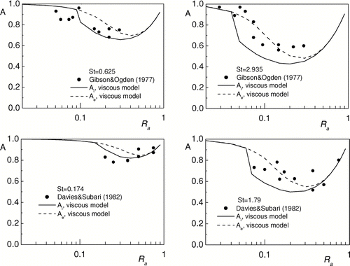
FIG. 6 The comparison of the dependencies A i (R a ) and A e (R a ) with experimental data from CitationGibson and Ogden (1977) and CitationDavies and Subari (1982).

FIG. 7 The comparison of the dependencies A i (R a ) and A e (R a ) with the aspiration efficiencies, obtained by the formulas from , for various values of St.
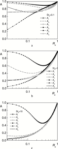
FIG. 7 The comparison of the dependencies A i (R a ) and A e (R a ) with the aspiration efficiencies, obtained by the formulas from Table 1, for various values of St.

FIG. 8 The cross-sectional area of the limiting particle trajectory surface far from the sampler at St = 1 and various R a .

FIG. 8 The cross-sectional area of the limiting particle trajectory surface far from the sampler at St = 1 and various R a .

FIG. 9 The particle trajectories at St = 1 for R a = 0.1. Dashed lines are the trajectories of particles deposited on the sampler surface.
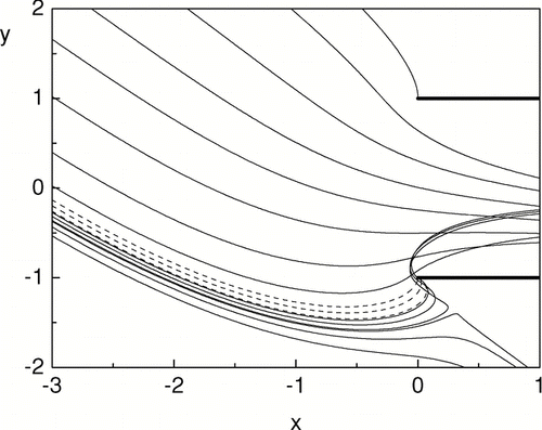
FIG. 9 The particle trajectories at St = 1 for R a = 0.1. Dashed lines are the trajectories of particles deposited on the sampler surface.

FIG. 10 The dependencies of the aspiration efficiency on R a with and without gravity influence for various St and fixed Fr (a) and for fixed St and various R c (b).
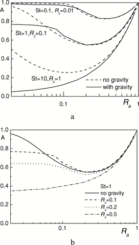
FIG. 10 The dependencies of the aspiration efficiency on R a with and without gravity influence for various St and fixed Fr (a) and for fixed St and various R c (b).

FIG. 11 The comparison of the numerical and approximate dependencies A(R a ) for calm air sampling.

FIG. 11 The comparison of the numerical and approximate dependencies A(R a ) for calm air sampling.

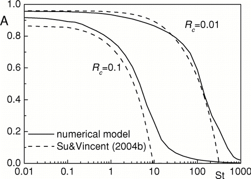
FIG. 12 The comparison of A(R a ), obtained from numerical model and approximate formula (8) for fixed Fr and various St (a) and for fixed St and various R c (b)
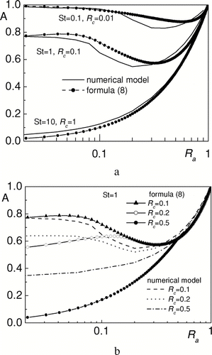
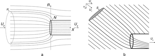
FIG. 12 The comparison of A(R a ), obtained from numerical model and approximate formula (8) for fixed Fr and various St (a) and for fixed St and various R c (b)
Reprints and Corporate Permissions

Please note: Selecting permissions does not provide access to the full text of the article, please see our help page How do I view content?

To request a reprint or corporate permissions for this article, please click on the relevant link below:

Academic Permissions

Please note: Selecting permissions does not provide access to the full text of the article, please see our help page How do I view content?

Obtain permissions instantly via Rightslink by clicking on the button below:

If you are unable to obtain permissions via Rightslink, please complete and submit this Permissions form. For more information, please visit our Permissions help page.