Figures & data
FIG. 1 Schematic of the electrostatic classification inlet.
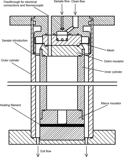
FIG. 2 Photograph of the filament coil mounted in the ceramic cylinder.
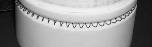
FIG. 3 Drawing of the model domain showing the relevant geometrical parameters and the limiting fluid streamlines and electric field lines.
FIG. 4 Plot of ideal collection efficiency curves for Q s /Q c = 0.1 and a range of filament lengths, Δ L.
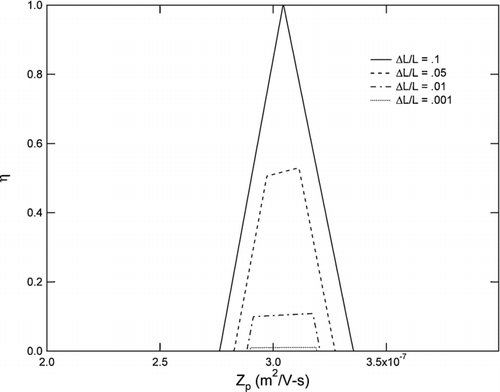
FIG. 5 Model results for a range of voltages, assuming an operating pressure of 10 Torr, Q s /Q c = 0.1, and L/Δ L = 30.
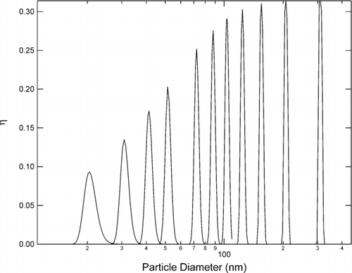
FIG. 6 Schematic of atmospheric pressure experiment.

FIG. 7 Schematic of low pressure experiment.
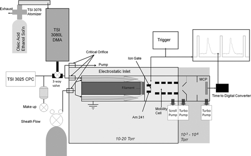
FIG. 8 Low pressure ion mobility spectra of laboratory air and oleic acid.
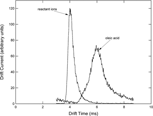
FIG. 9 Atmospheric pressure data for a cylinder voltage of 100, 200, and 300 Volts compared with model.
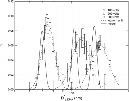
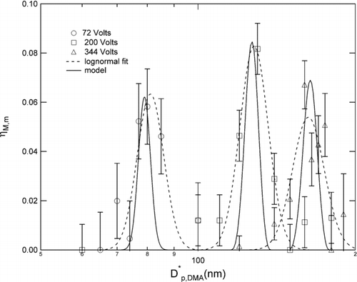
FIG. 10 Low pressure data for a cylinder voltage of 71, 200, and 344 Volts compared with model.